J3 Assembly
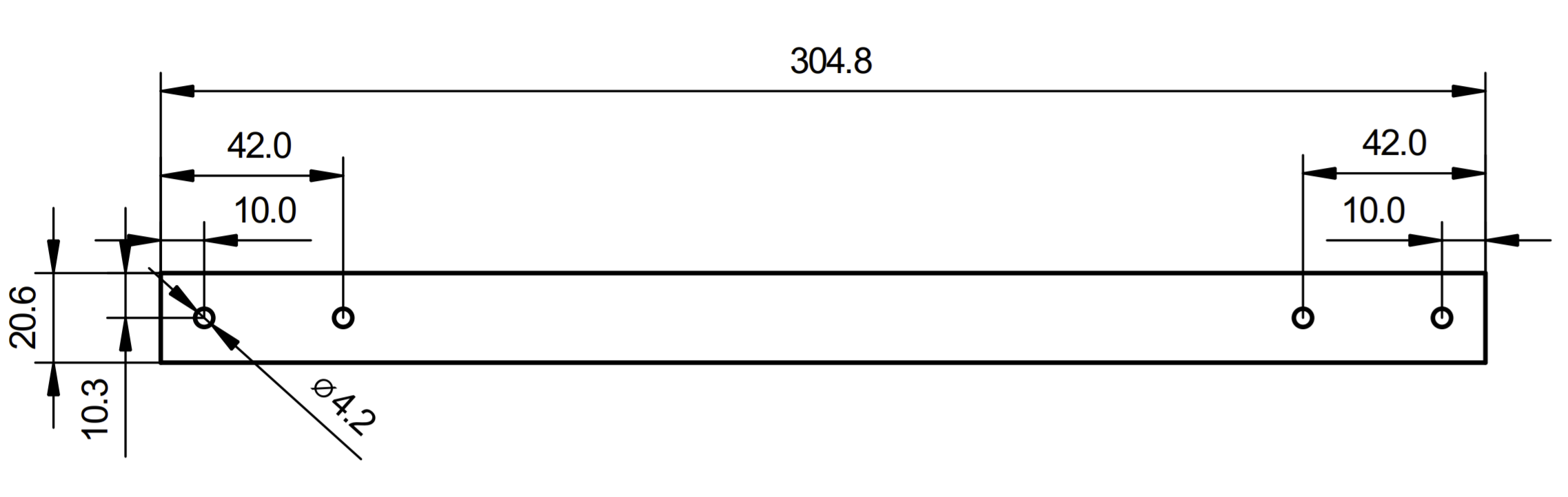
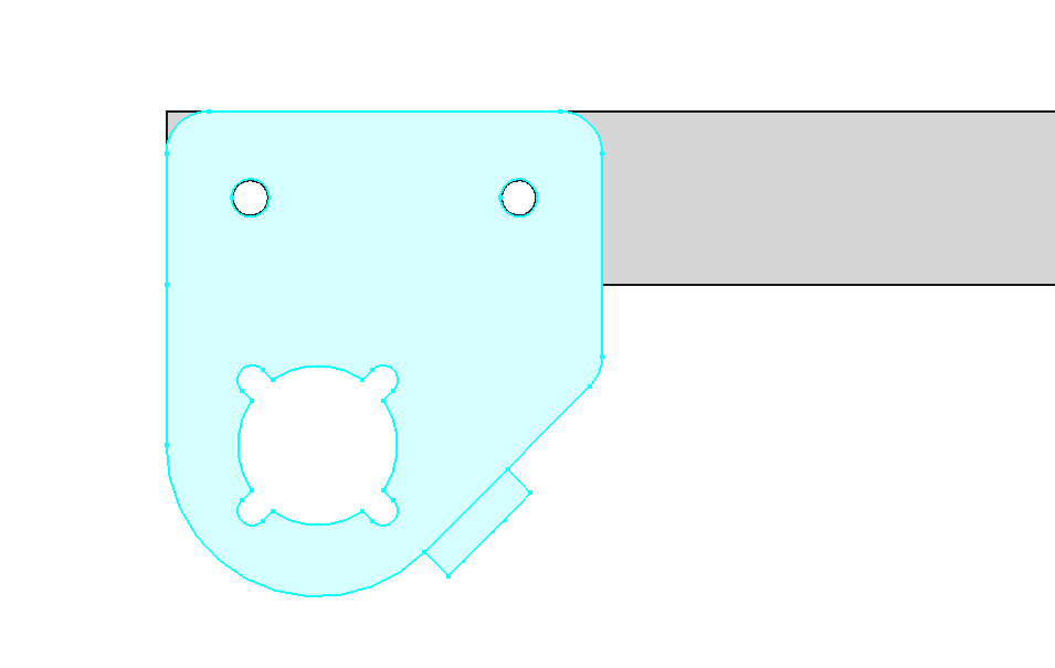
Drill Holes in Radius
If you didn't buy the radius with holes, you have to drill them according to the dimensions below. If you have holes in your radius already, skip to the next step.
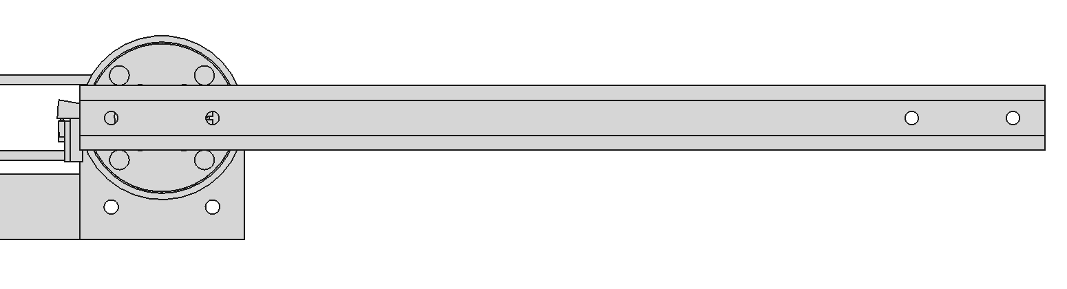
Attach the Radius to J2 Plate
Use 2 M4x6 screws to attach the radius to the J2 plate. Apply thread locker to the screws.
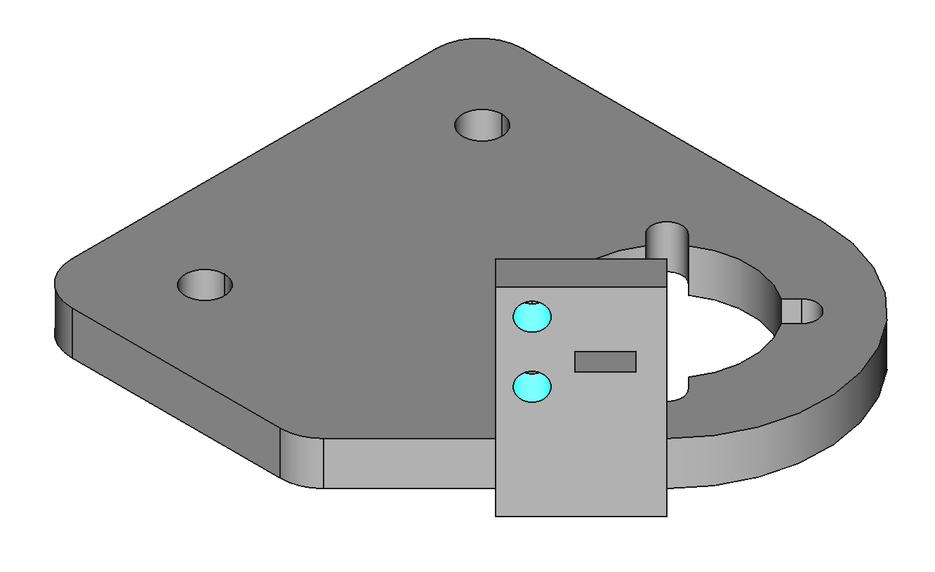
Add Heat-Set Inserts to J3 Base
The J3 base needs 2 M2 heat-set inserts for mounting the home switch.

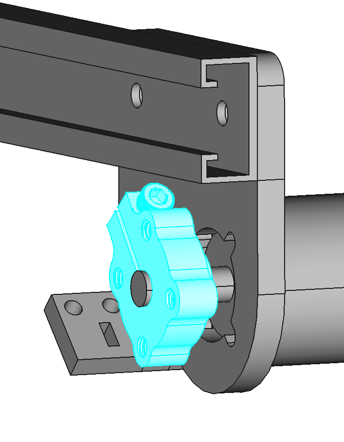
Mount J3 Base on Radius
Use 2 M4x12 screws and nylon lock nuts. Use thread locker on the screws.
Mount J3 Motor to J3 Base
Use 4 M3x8 button head screws. Apply threadlocker to the screws.
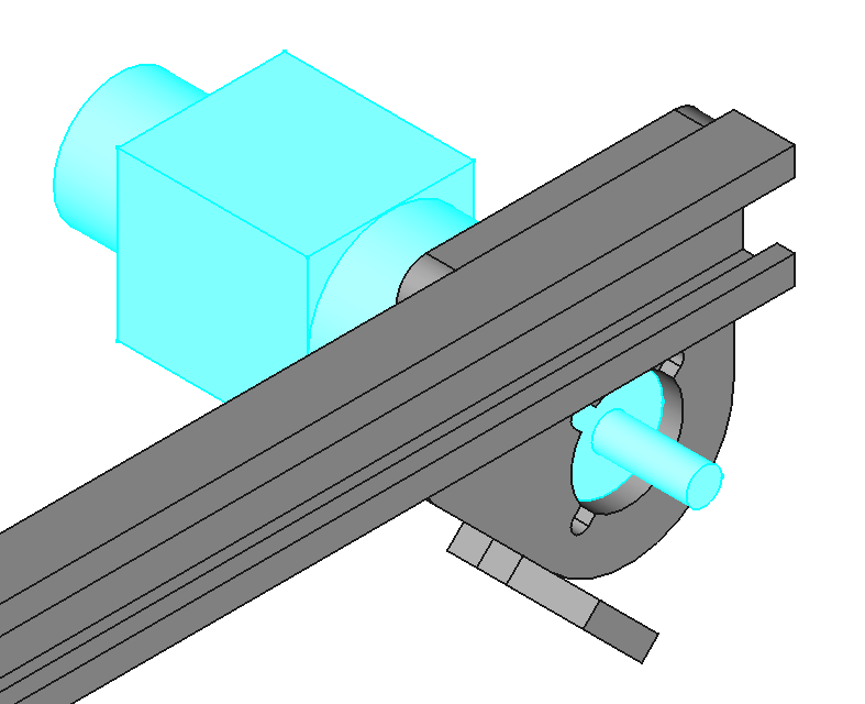
Attach Hub to J3 Motor
Space the hub 5mm from the J3 base. Use threadlocker on the hub clamping screw.
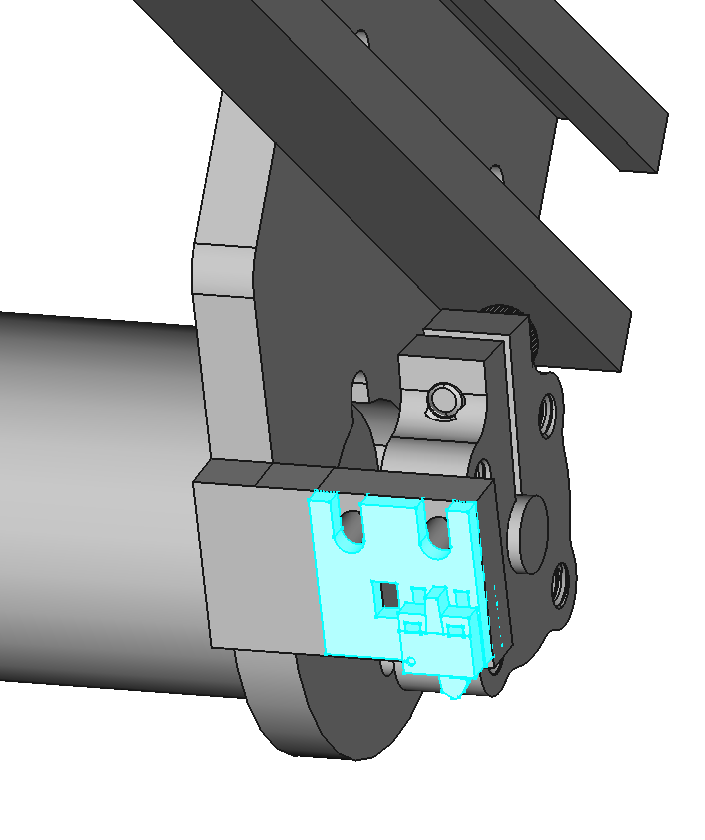
Mount a Home Switch to Base J3
Use M2x5 screws to mount home switch variation A to base J2 (PCBA-HOME-A-1.0).