J0 Assembly
Add Heat-Set Inserts to J0 Base
J0 Base needs 2 M2 heat-set inserts for mounting the home switch.


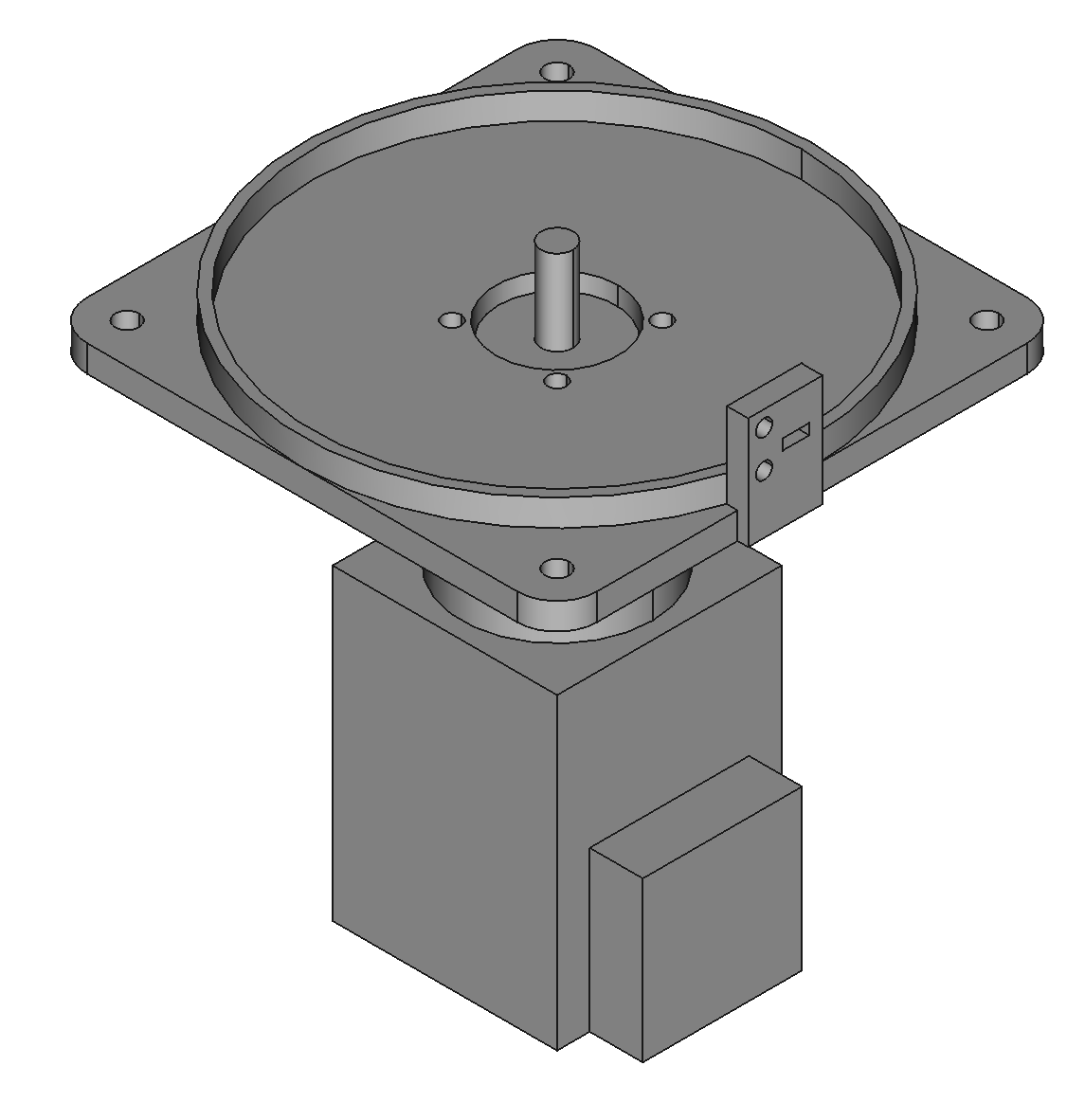
Mount Motor J0 to J0 Base
Use 4 M3x8 button head screws. Apply threadlocker to the screws.


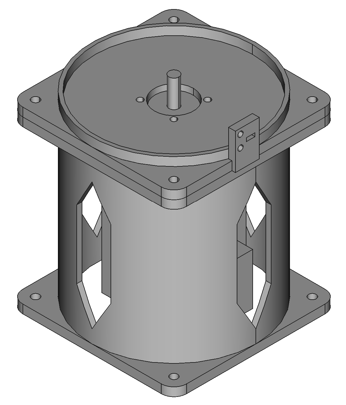
Mount J0 Base to the Riser
Use 4 M4x16 screws and nylon locknuts. Push the motor cables through the riser vent toward the PCBA.

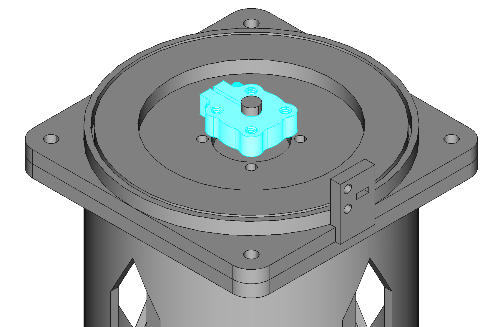
Attach the 6mm Bore Clamping Hub to Motor J0
Point the raised feature of the hub (HUB-545616) down, space the hub from the J0 base using the 3mm spacer.

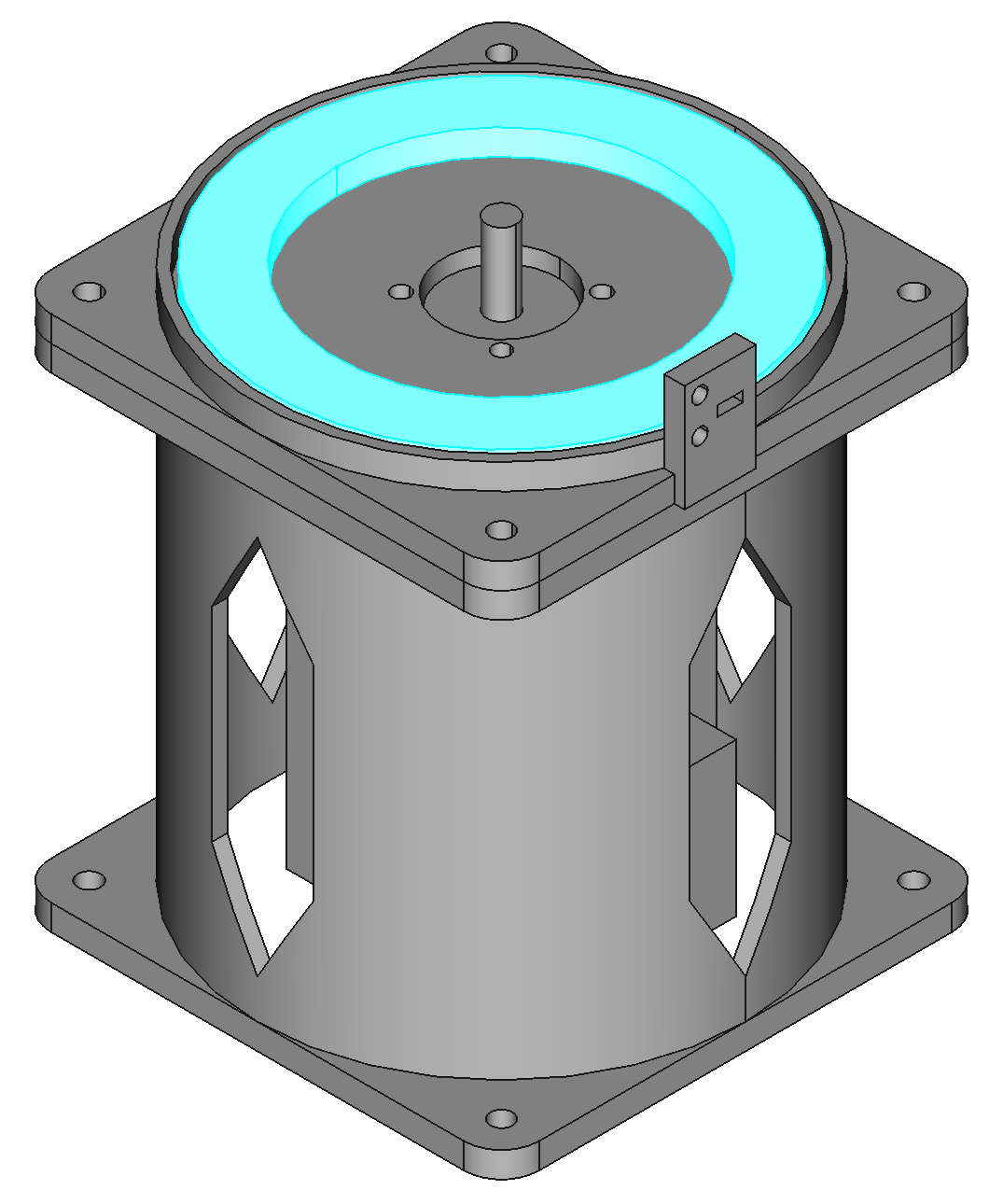
Place Thrust Bearing in J0 Base
The 65mm ID 90mm OD needle roller thrust bearing goes in the J0 base (THRUST-65-90)

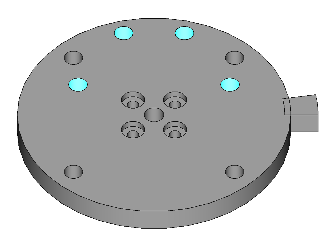
Add Heat-Set Inserts to J0 Plate
The J0 plate requires 8 M4 heat-set inserts. 4 of these go in the bottom for the stabilization set screws. 4 go in the top to mount base J1 to J0 plate.
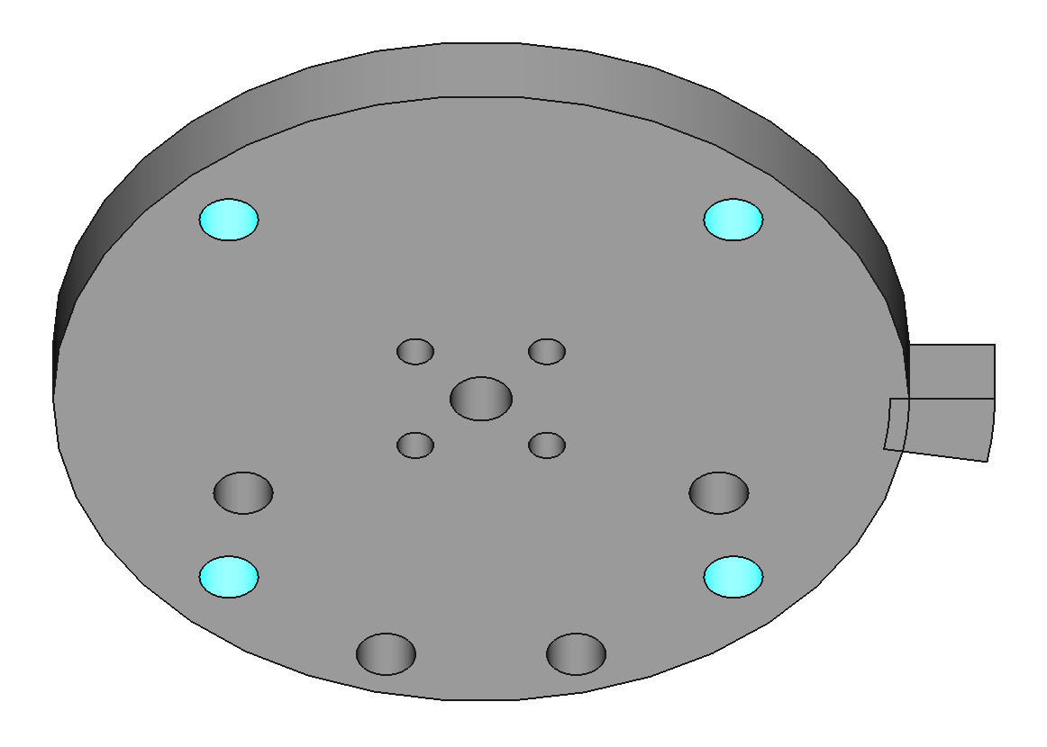

Add Set Screws and Nuts to J0 Plate
These set screws stabilize J0 plate against the thrust bearing. The nuts must be in place to lock the position of the set screws in a later step. The nuts go on the bottom of J0 plate.

Attach J0 Plate to the Hub
Use #6x0.5" button head screws to attach J0 plate to the hub. Apply thread locker to the screws. Make sure the set screws do not touch the thrust bearing yet.
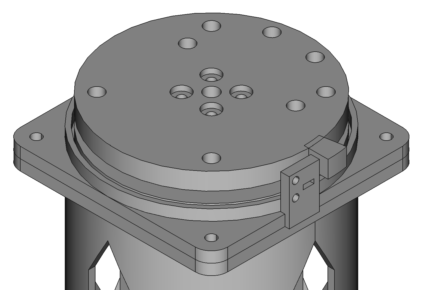

Tighten J0 Plate Set Screws
Lightly tighten the set screws in the J0 plate to touch the thrust bearing. Overtightening will bend the J0 plate. Once the set screws are touching the thrust bearing, tighten the nuts against the J0 plate to lock the set screws in place.

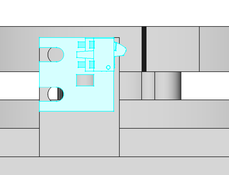
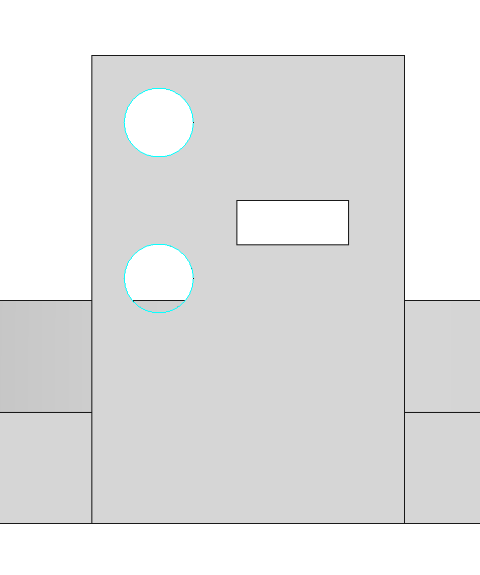
Mount a Home Switch to J0 Base
Use M2x5 screws to mount home switch variation A to the J0 base (PCBA-HOME-A-1.0).