J2 Assembly
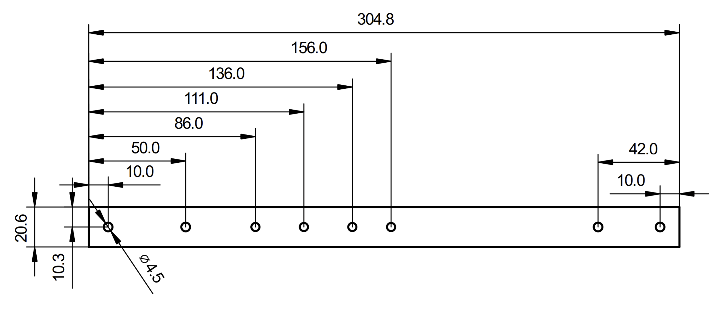
Drill Holes in Humerus
If you didn't buy the humerus with holes, you have to drill them according to the dimensions below. If you have holes in your humerus already, skip to the next step.
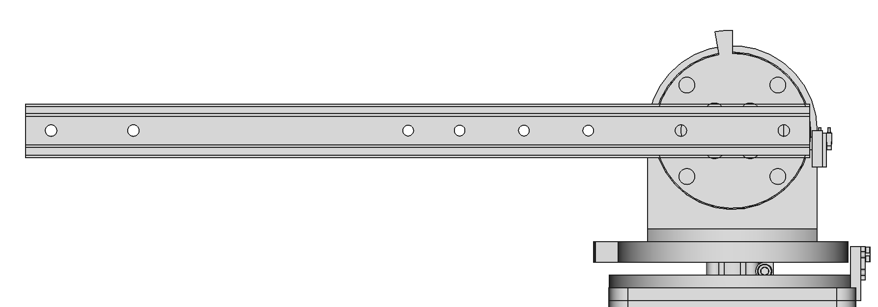
Attach the Humerus to Plate J1
Use 2 M4x6 screws to attach the humerus to plate J1. Apply thread locker to the screws.
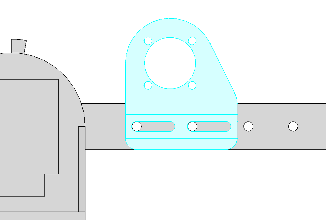
Attach J2 Motor Bracket to Humerus
Use 2 M4x20 screws with oversize M4 washers and nylon-insert locknuts to attach the J2 motor bracket to the humerus. The oversize washers prevent the screws from making impressions in the plastic slots.


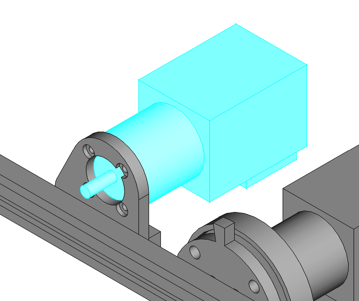
Mount J2 Motor to J2 Motor Bracket
Use 4 M3x8 button head screws. Apply threadlocker to the screws.
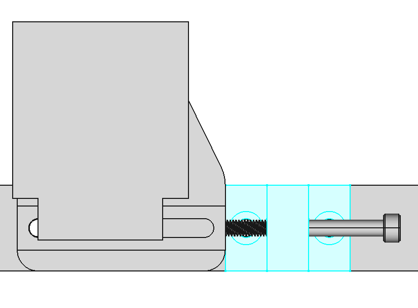
Mount Tensioner to Humerus
Use 2 M4x12 flat head screws and 2 nylon-insert locknuts to mount the tensioner on the humerus. Then slide an M4x40 screw through the tensioner with a nylon-insert locknut.

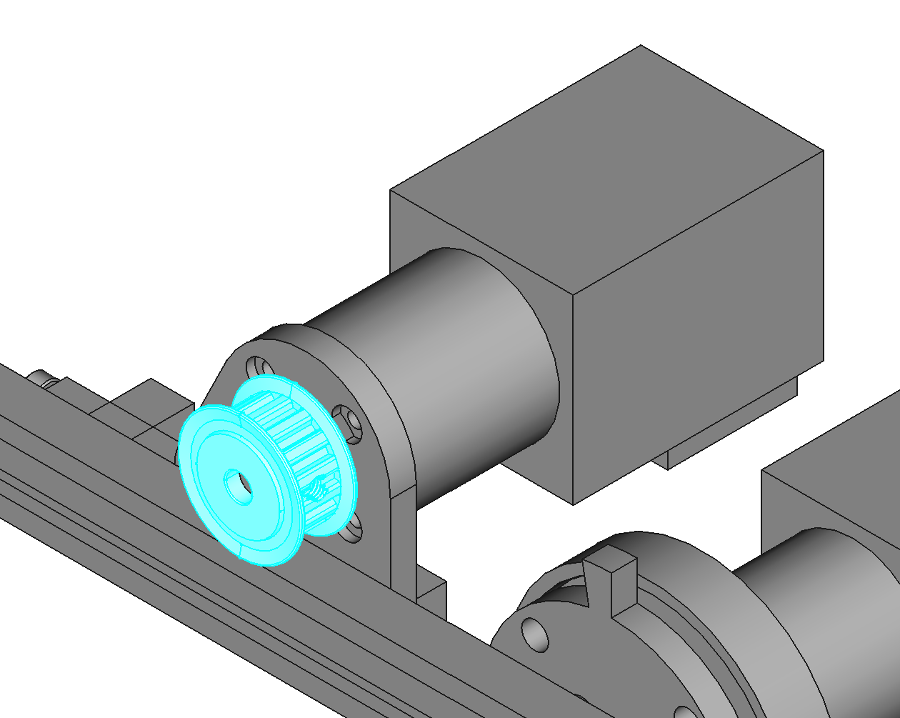
Mount Pulley on Motor J2
Apply thread locker to the set screw of PULLEY-615432 and tighten it on the flat of the motor shaft. Space the pulley slightly away from the motor bracket using a washer.

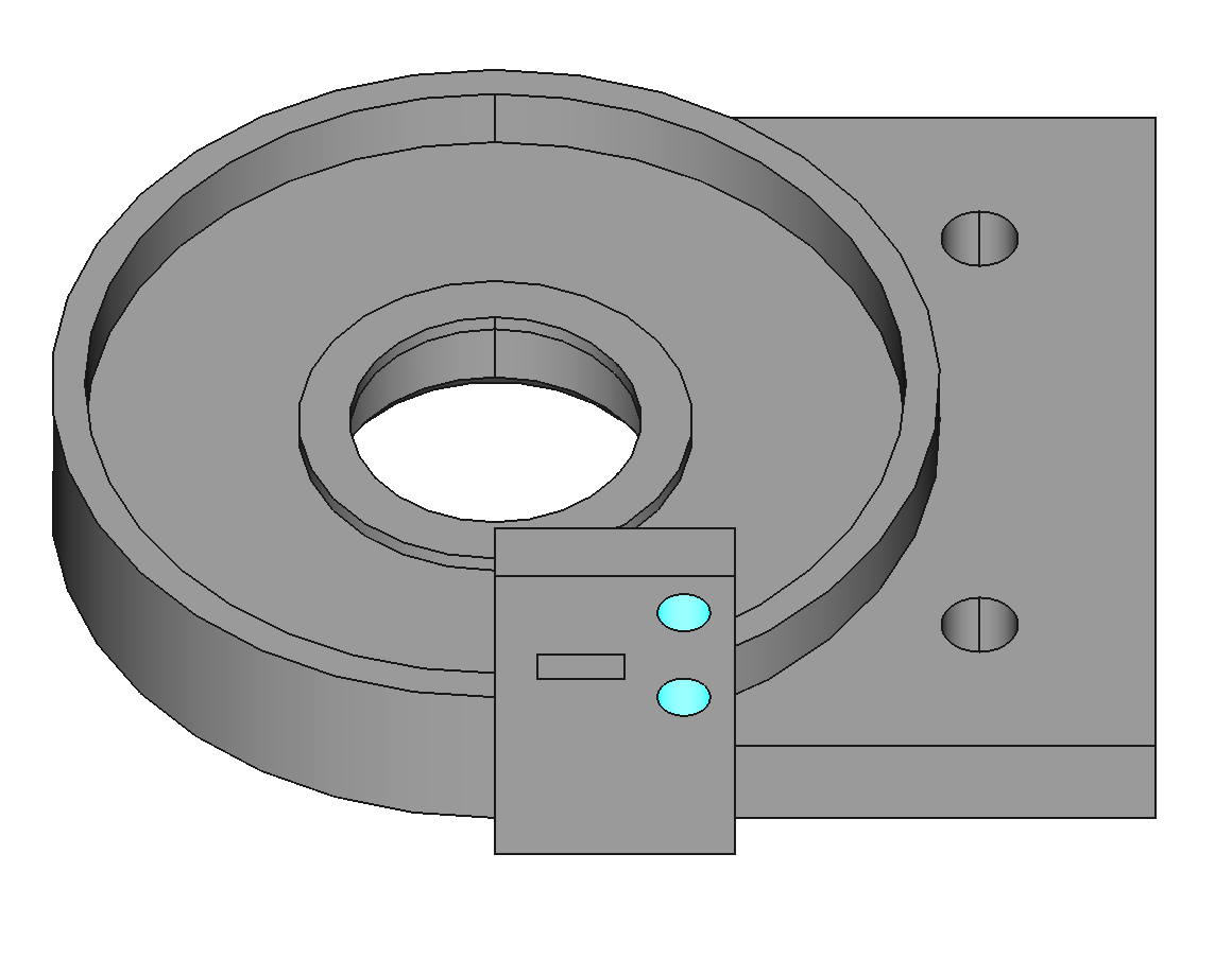
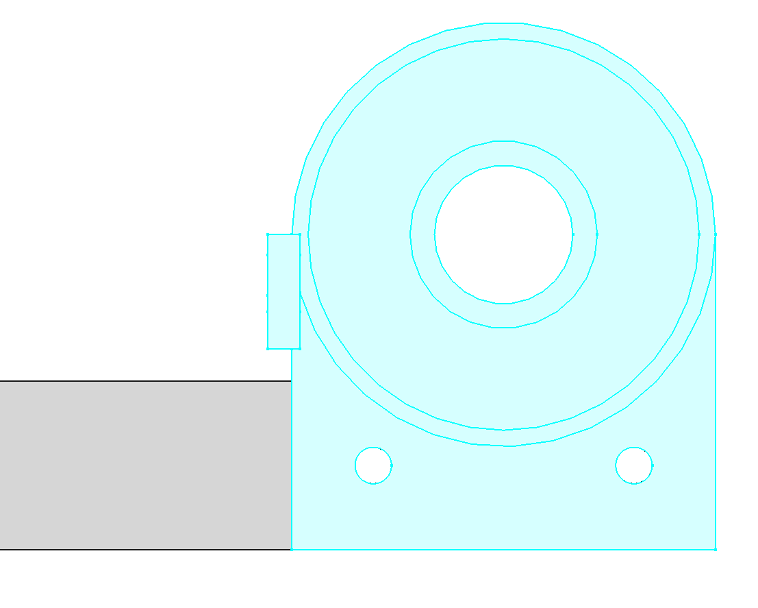
Add Heat-Set Inserts to J2 Base
The J2 base needs 2 M2 heat-set inserts for mounting the home switch.

Mount J2 Base on Humerus
Use 2 M4x12 screws and nylon-insert locknuts.
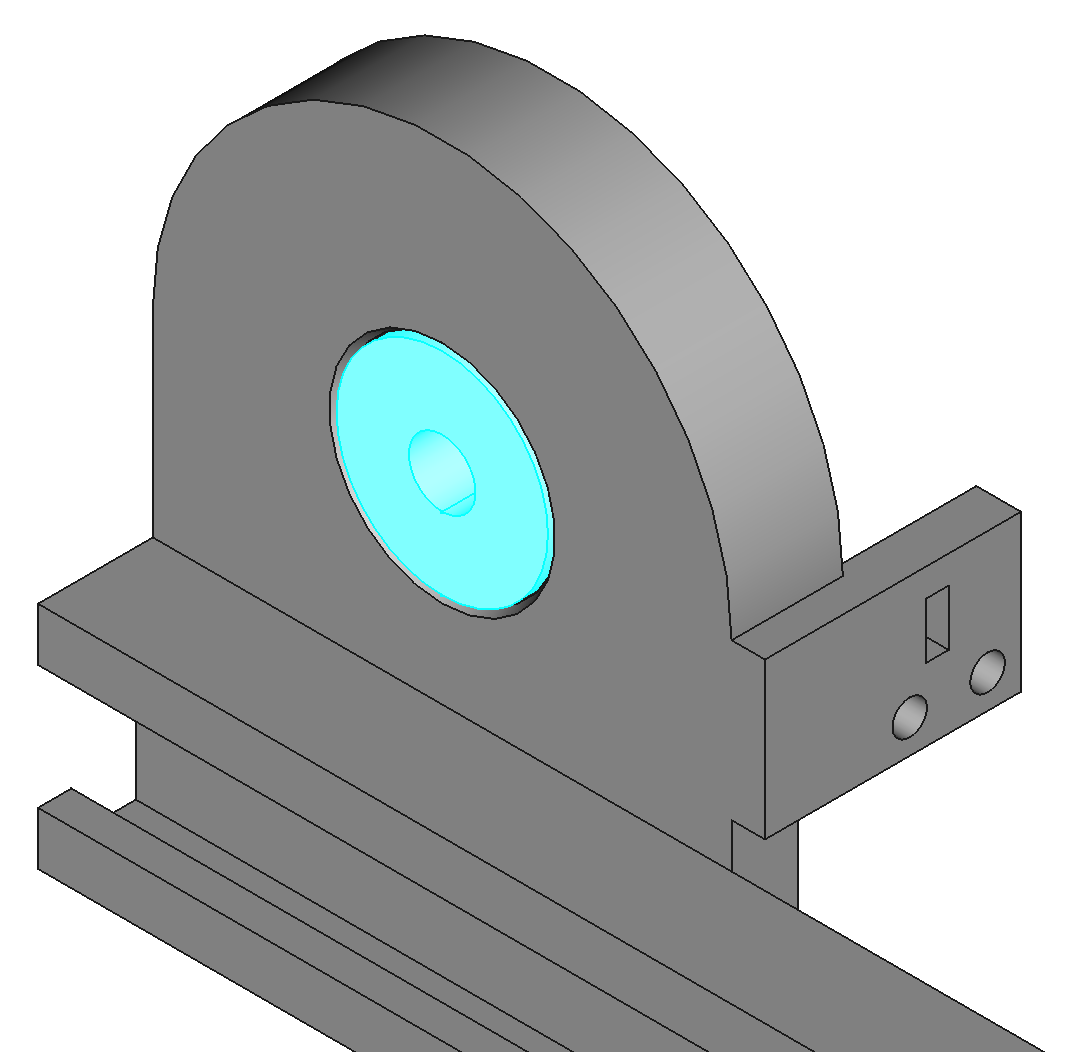
Push Ball Bearing into J2 Base
The ball bearing (BALL-6-19-6) should slide into base J2 as a slip fit. It may be more of a press fit depending on the accuracy of the 3D printer used. If you have trouble pushing it in, you can file the hole, or try heating the hole with a heat gun to make it expand and soften.

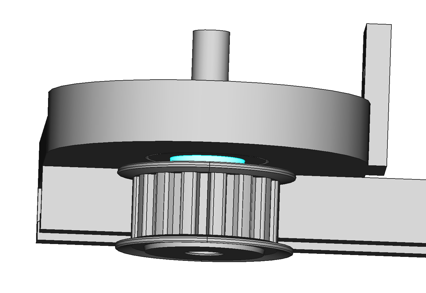
Mount Pulley on J2 Shaft
Mount PULLEY-615433 flush with one end of the J2 shaft. Tighten the set screw on the flat of the shaft. Use thread locker. Slide an M6 washer onto the shaft and slide the shaft through the inner diameter of the ball bearing. The washer ensures the pulley will not rub on the plastic of J2 base.
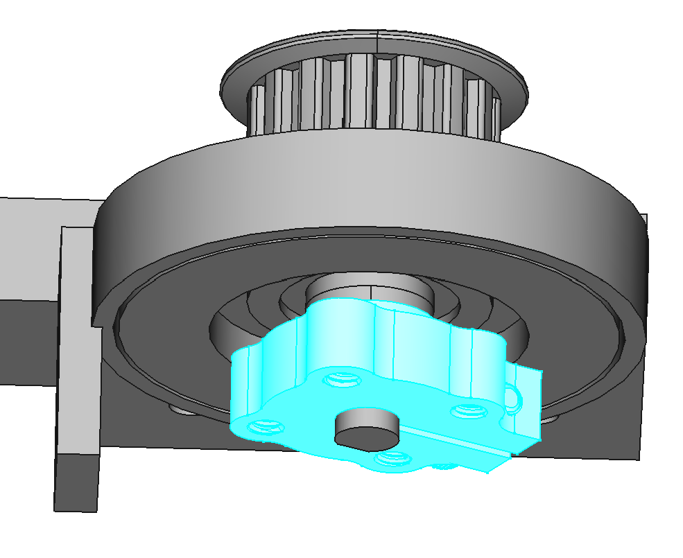
Add Thrust Bearing to J2 Base
Place the thrust bearing (THRUST-30-47) in the J2 base. You will probably have to hold it in place while you put the hub on in the next step.
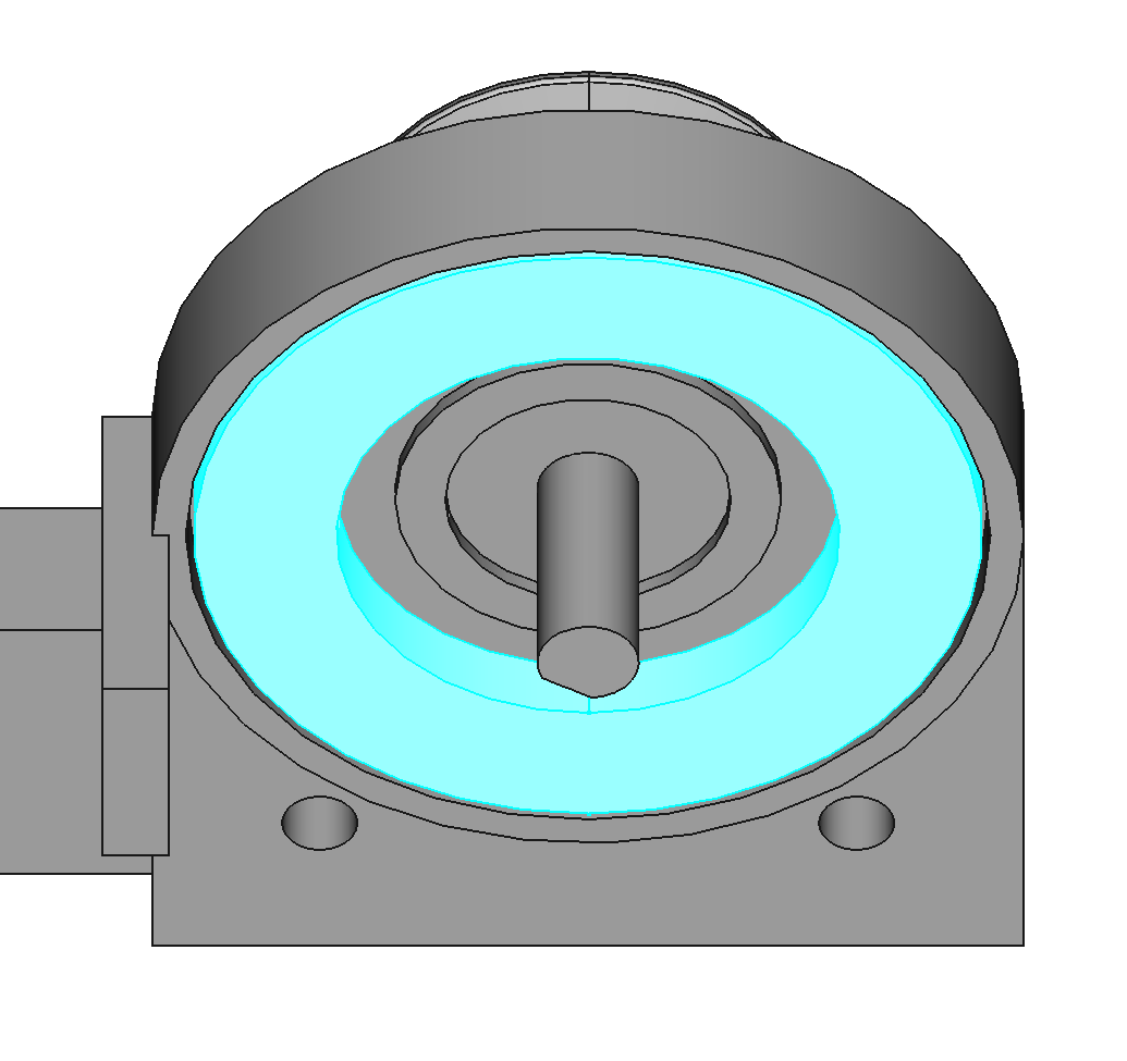
Attach Hub to J2 Shaft
Use an M6 washer to space the hub from the ball bearing, then tighten the hub on the shaft. Use threadlocker on the hub clamping screw.
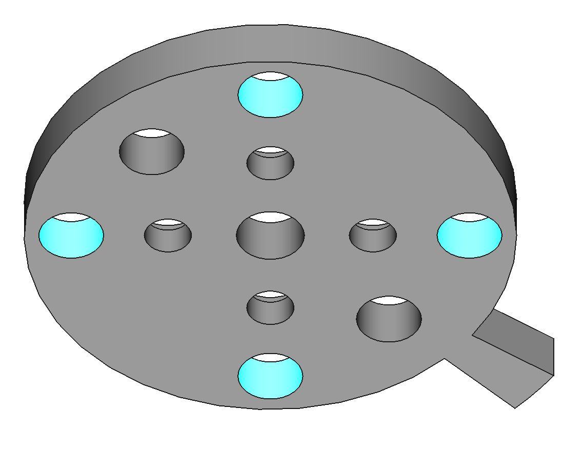
Add Heat-Set Inserts to J2 Plate
The J2 plate requires 6 M4 heat-set inserts.
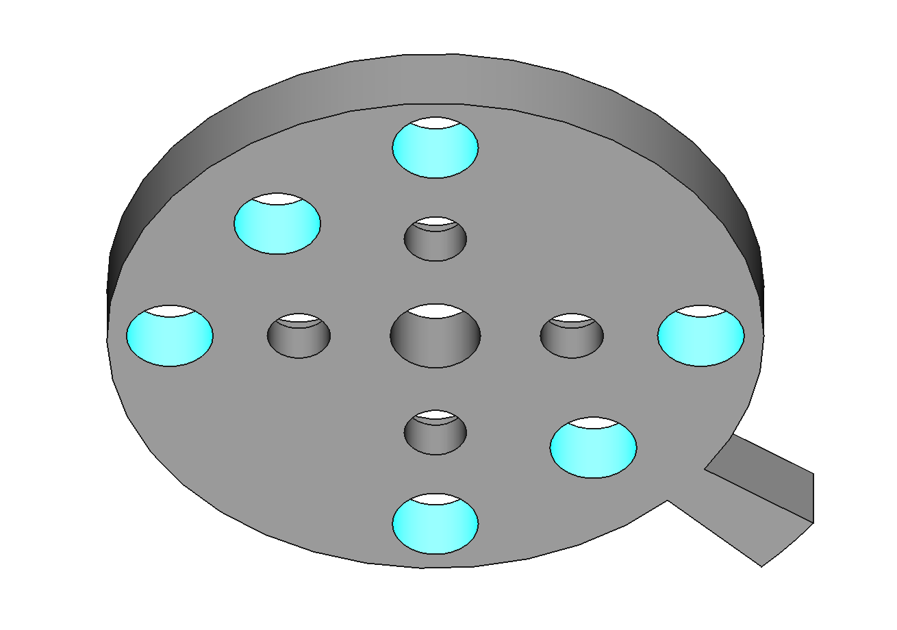

Add Set Screws and Nuts to Plate J2
Use M4x12 set screws. These set screws stabilize plate J2 against the thrust bearing. The nuts must be in place to lock the position of the set screws in a later step. The nuts go on the bottom of plate J2.

Attach J2 Plate to Hub
Use #6x3/8 button head screws to attach the J2 plate to the hub. Apply thread locker to the screws. Make sure the set screws in the J2 plate do not touch the thrust bearing yet.
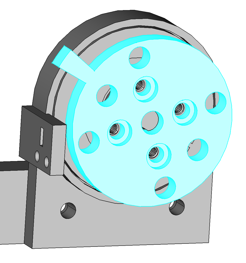
Tighten J2 Plate Set Screws
Lightly tighten the set screws in the J2 plate to touch the thrust bearing. Overtightening will bend the J2 plate. Once the set screws are touching the thrust bearing, tighten the nuts against the J2 plate to lock the set screws in place.

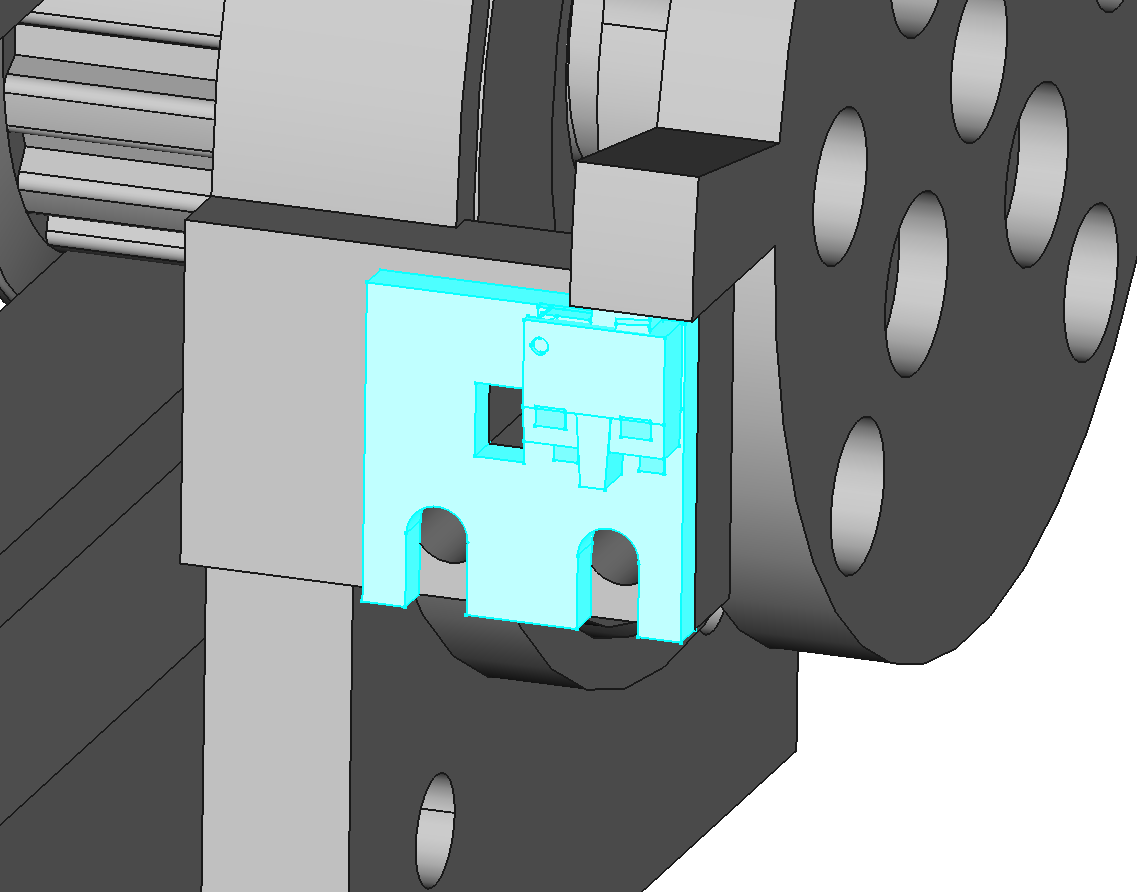
Mount Home Switch to J2 Base
Use M2x5 screws to mount home switch variation B to the J2 base (PCBA-HOME-B-1.0).

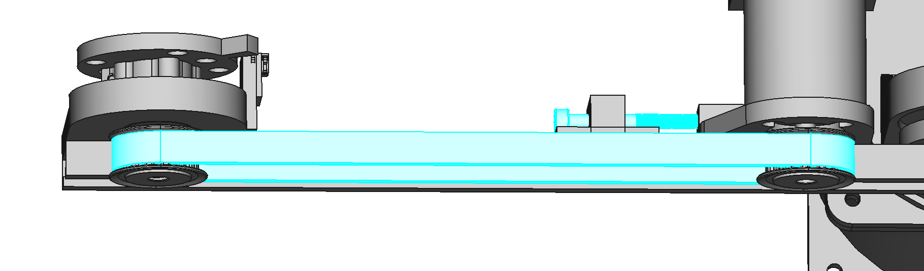
Tension Belt
Put the belt over the two pulleys. Loosen the screws holding the J2 motor bracket to the humerus. Tighten the tensioner screw until the belt is taught. Retighten the screws holding the J2 motor bracket to the humerus.