Base Assembly
The base can be a piece of plywood, or a tabletop that you're willing to drill holes in. The CAD model shows a 24 inch square piece of plywood that is 0.5 inches thick.

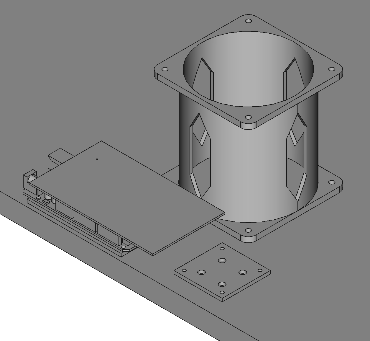
Drill Holes in the Base
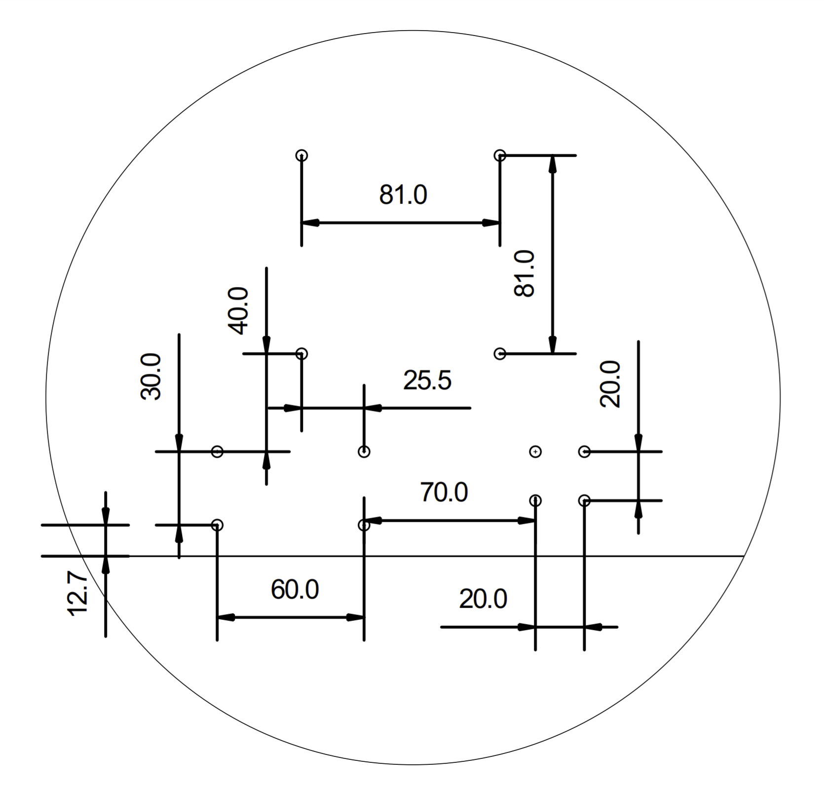
The base needs holes for the arm and 2 printed circuit boards. The PCBs only really need 2 holes, but the arm should have all 4. Use a 4.5mm drill bit. You can print this PDF to use as a template for the holes: BASE-1TO1-1.0.pdf


Mount the Riser to the Base
Use M4x25 screws with nylon lock nuts and oversize washers to mount the riser to the base. The oversize washers will prevent the screws from digging into the plywood.


Add Standoffs to PCB Brackets
Add M2.5 standoffs to the PCB brackets using nuts on the bottom of the brackets.

Mount the PCB Brackets to the Base
Use M4x25 screws and nuts with oversize washers.

Mount Microcontroller and DC Driver to Brackets
Use 4 M2.5 screws to mount the Arduino Mega (or clone) to its bracket. Do the same for the DC motor driver.

Push PCBA into Arduino
Push the main PCBA into the Arduino Mega (A4-PCBA-1.0).
