Motion Assembly
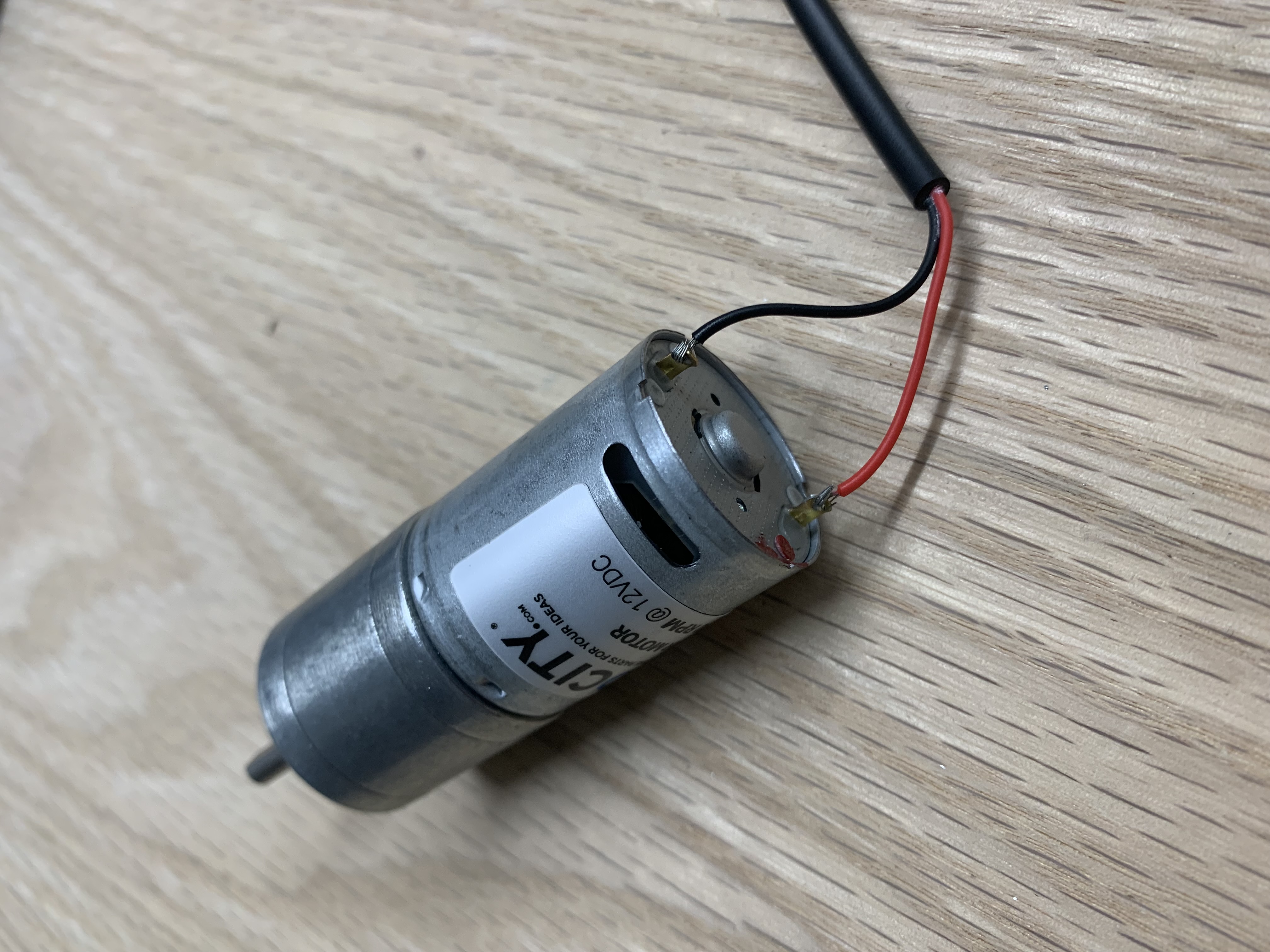
Solder the Motor Cable to the Motor
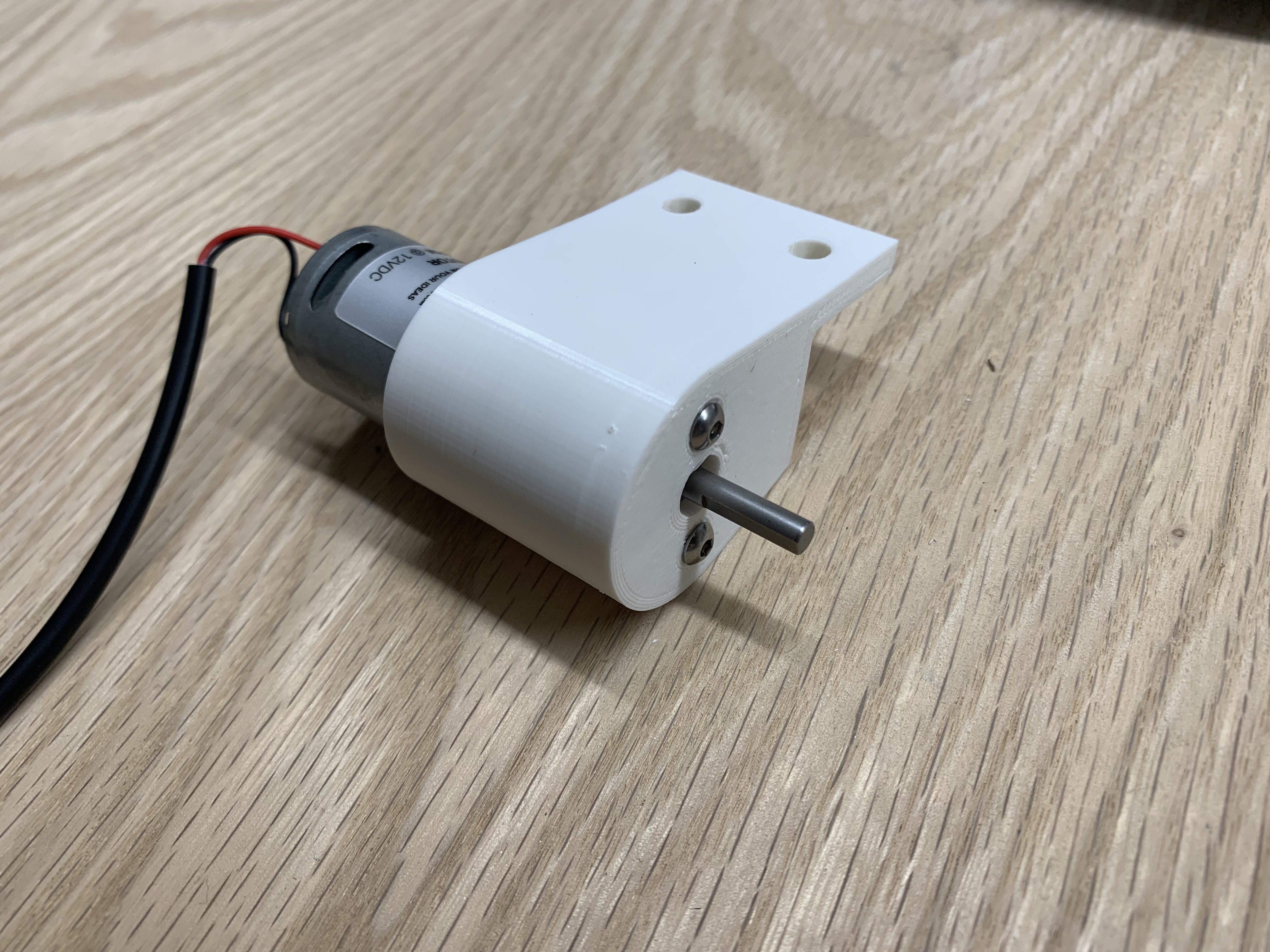
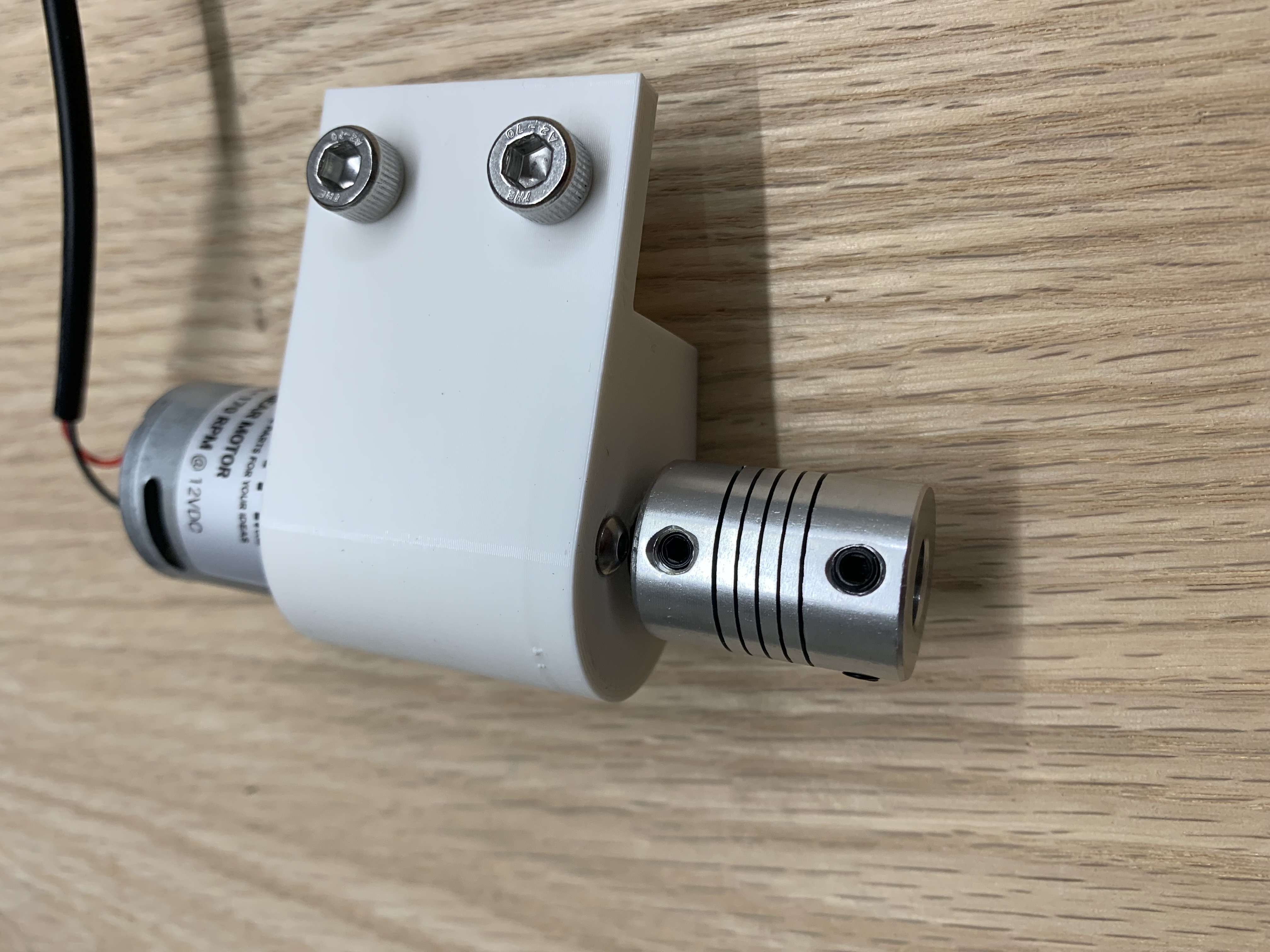
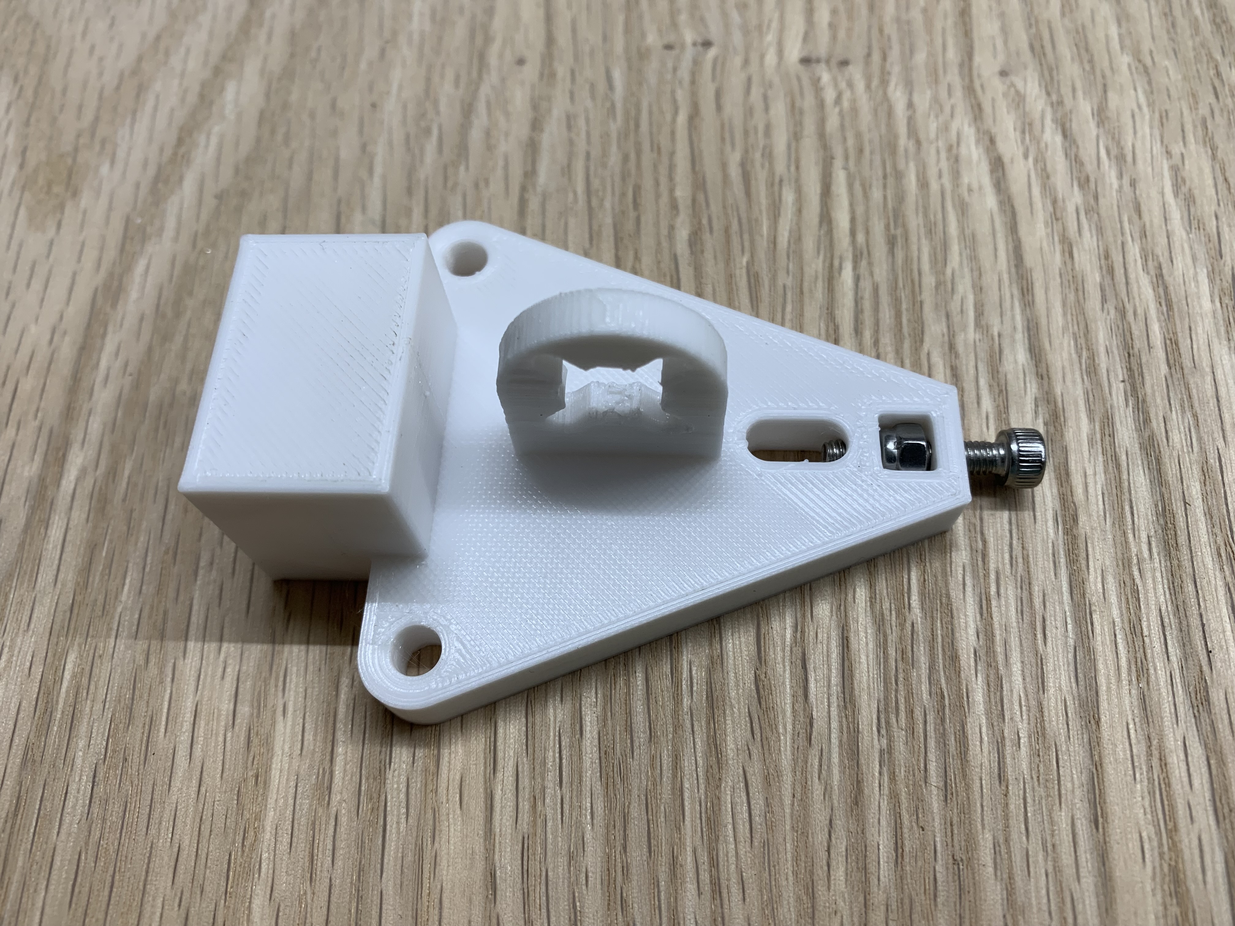
Install the Motor in the Motor Bracket
Use 2 M3x8 button head screws to fasten the motor to the motor bracket.
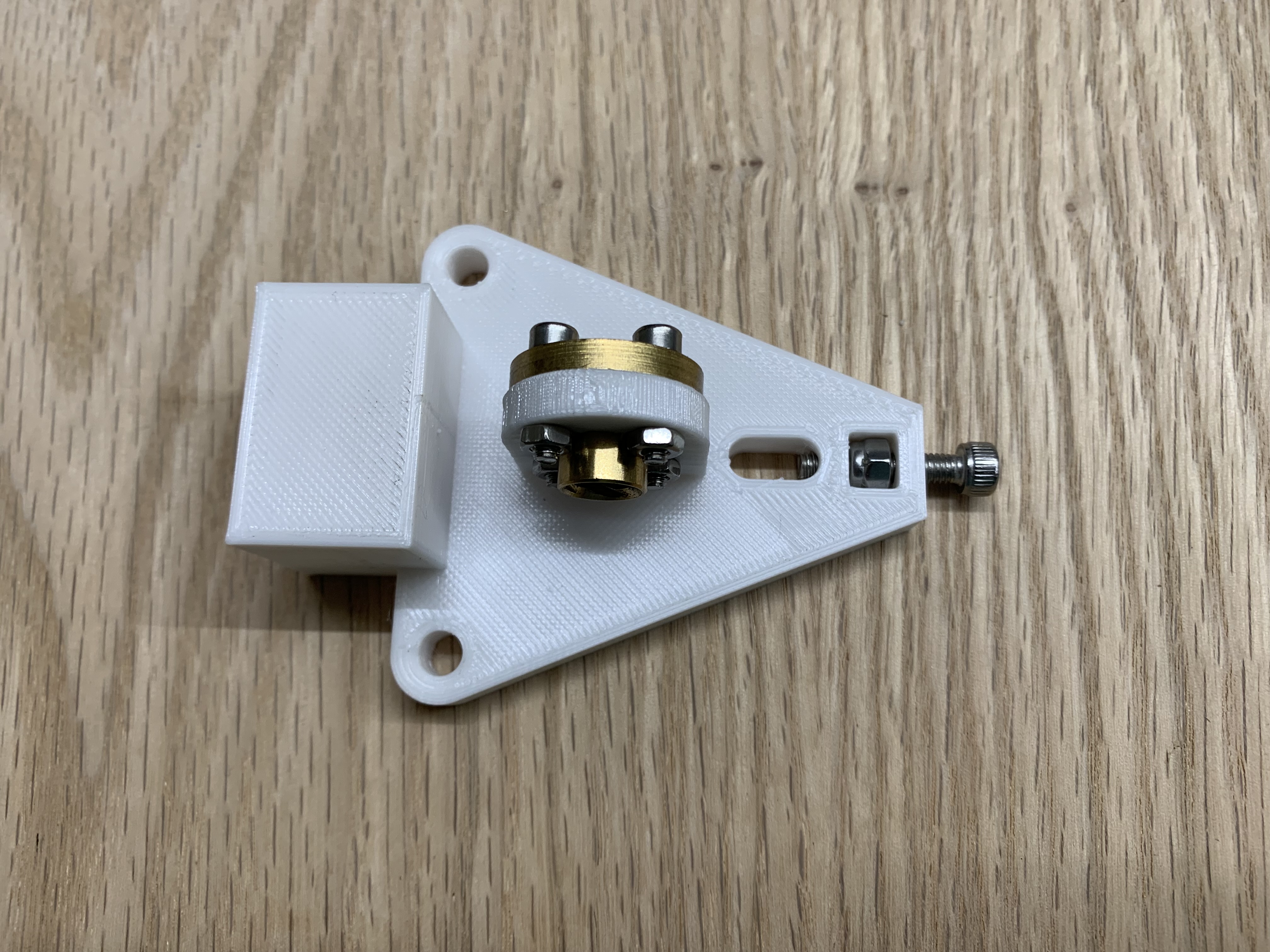
Mount the Coupler on the Motor Shaft
Tighten the set screws on the 4mm to 8mm coupler on the motor shaft. Make sure it is spaced to not rub the motor mounting screws.
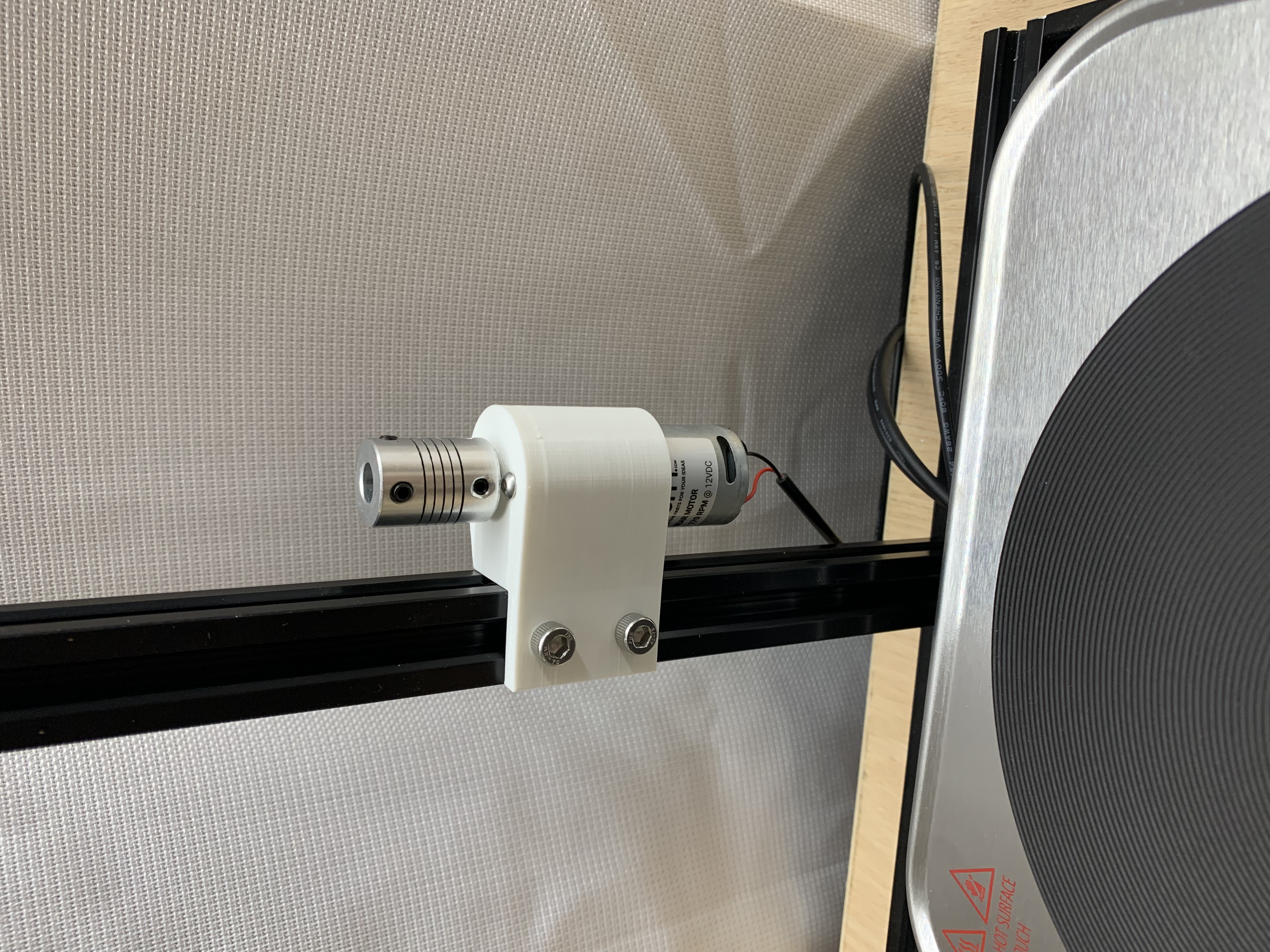
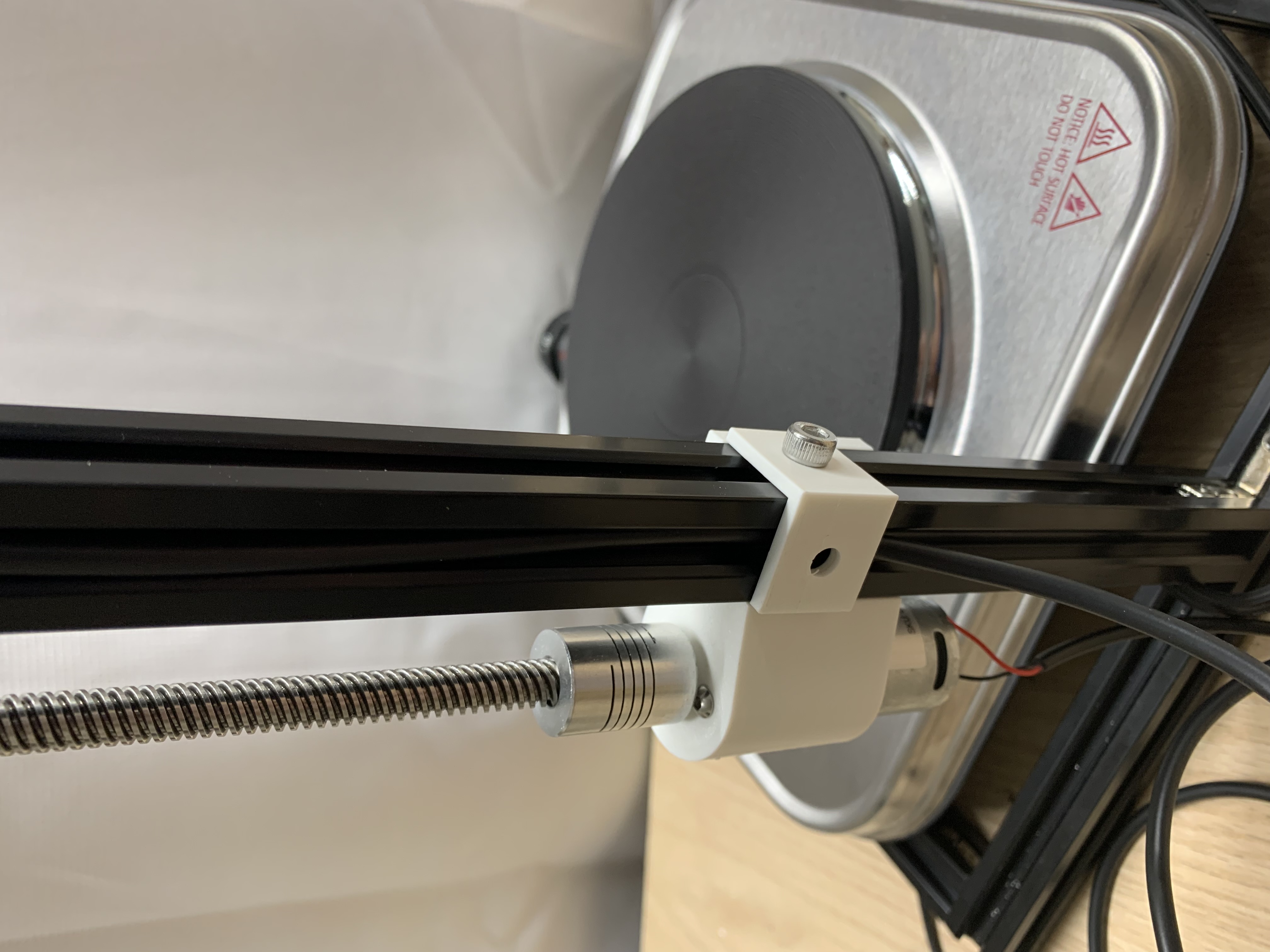
Mount the Motor Bracket on the Frame
Use 2 M5x8 screws and M5 T-nuts to mount the motor bracket near the bottom of Bar B.
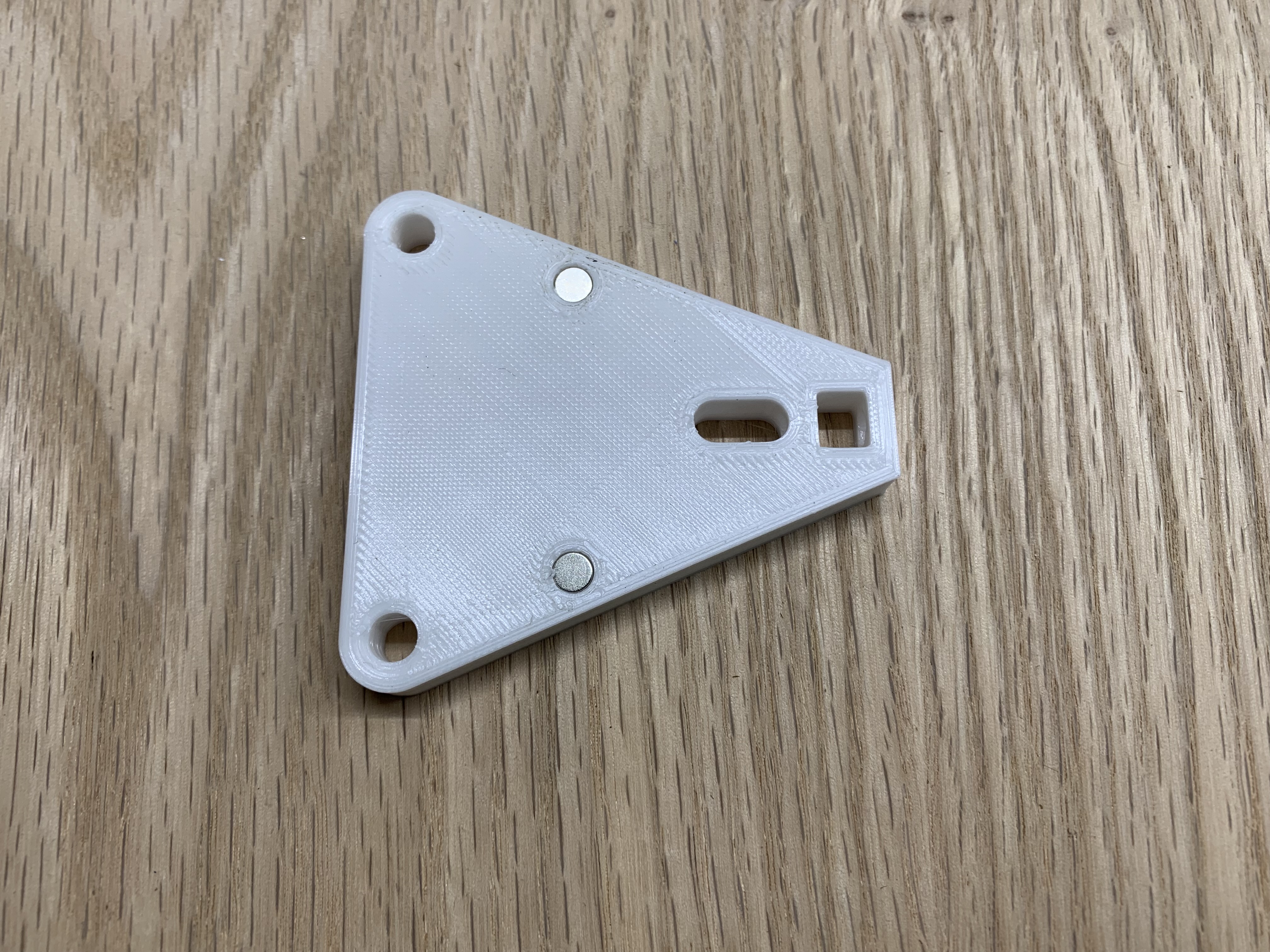
Glue Magnets in the Carriage Plate
Glue 2 0.125in diameter magnets into the carriage plate.
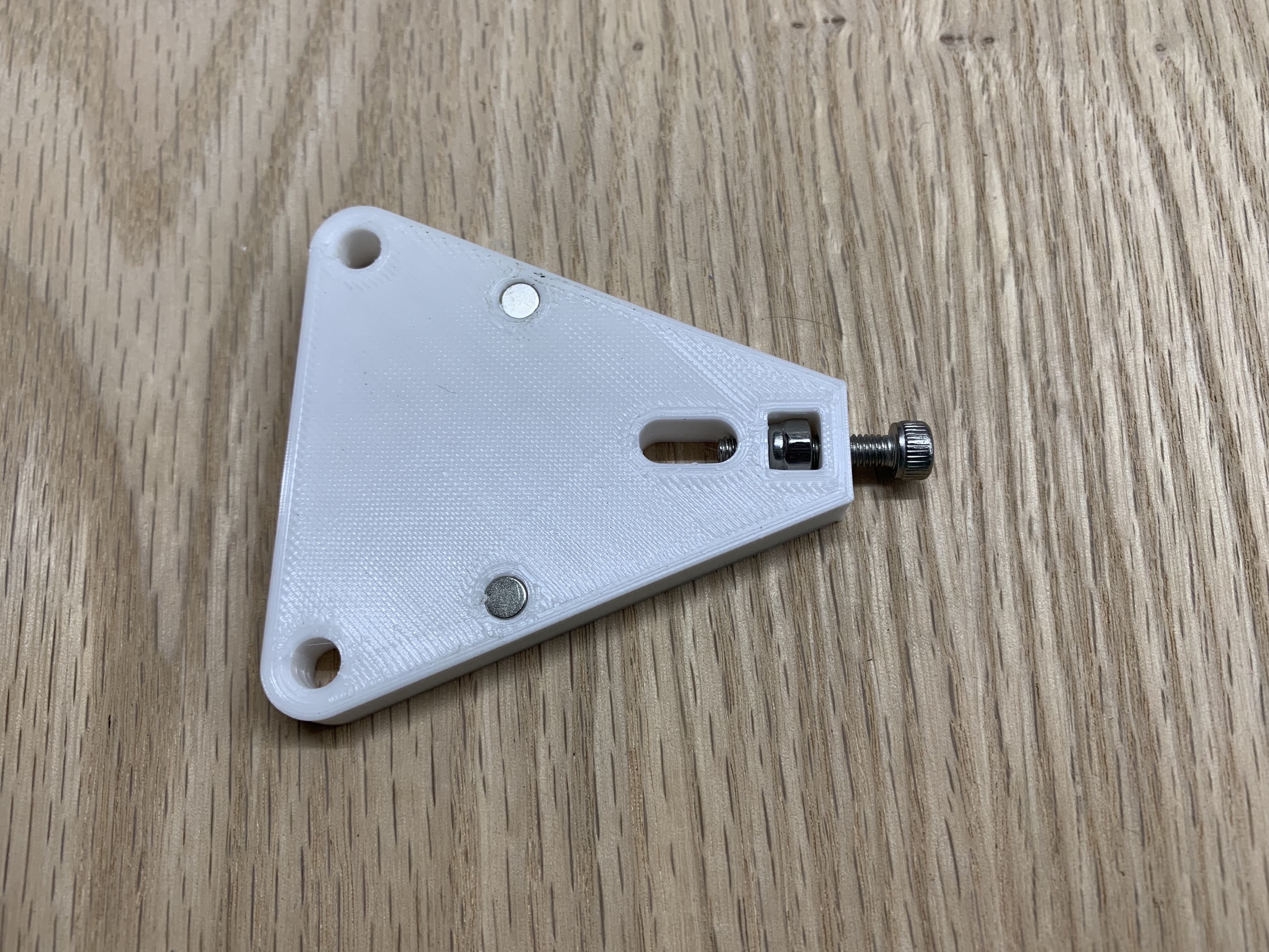
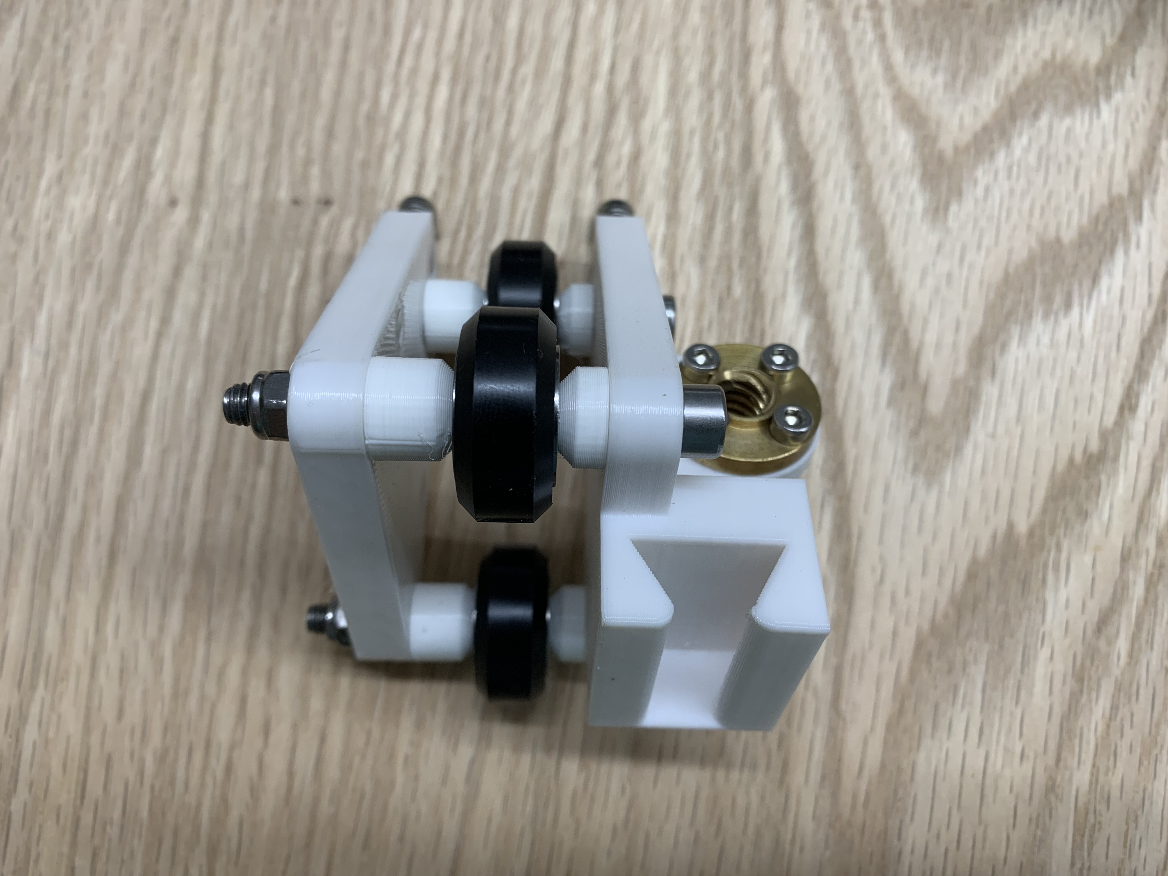
Add the Adjustment Screw
Add an M4x20 screw with nylon lock nut to the carriage plate. This adjusts the position of the back V-wheel to secure the wheels in the V slots. Do the same for the carriage.
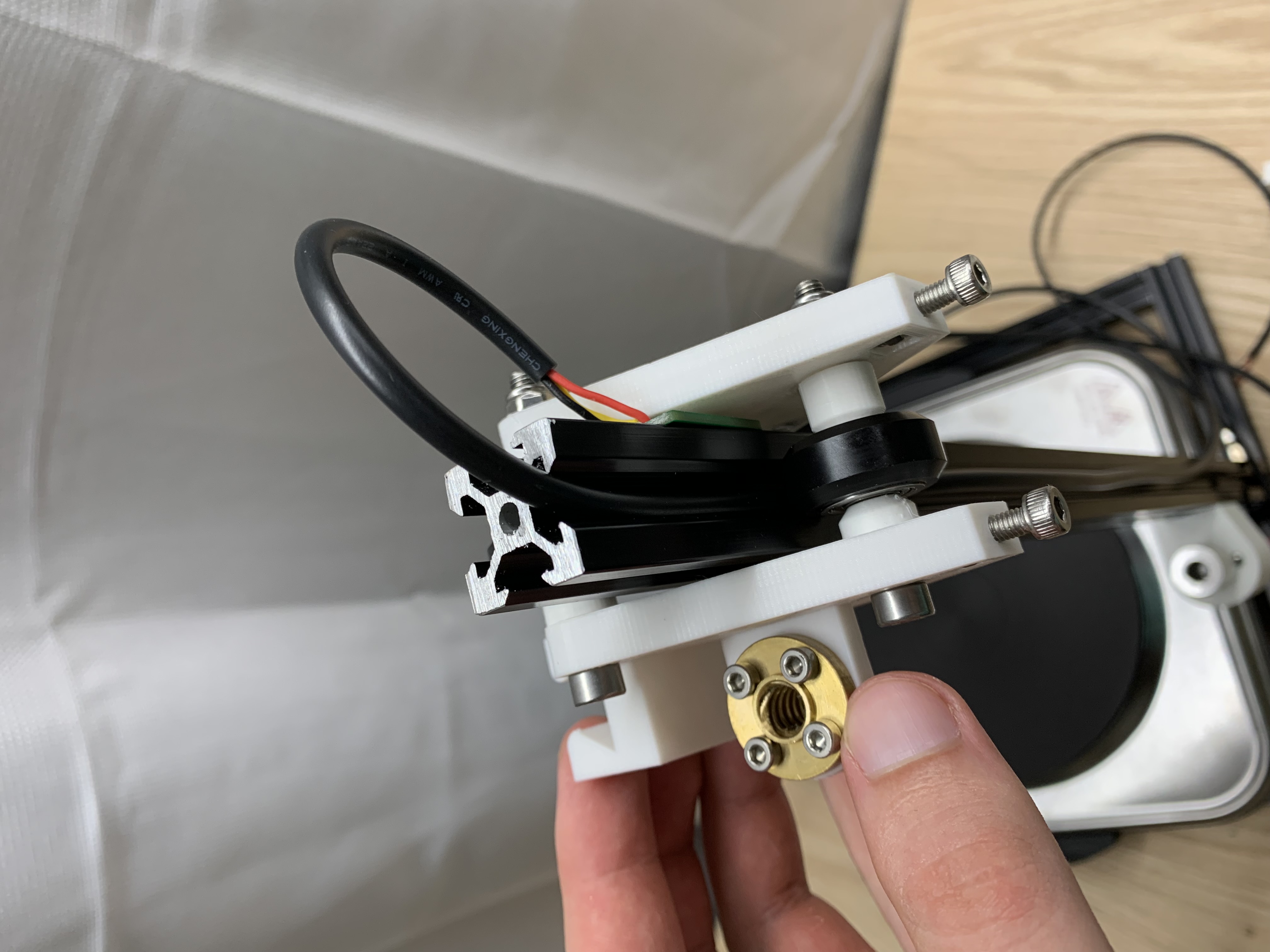
Attach the Lead Screw Nut to the Carriage
Use 4 M3x12 screws and nuts.
Assemble the V-Wheels
Use 3 M5x50 screws and nylon lock nuts to pinch the V-wheels between the carriage and carriage plate. Spacer A goes next to the carriage, and spacer B next to the carriage plate.
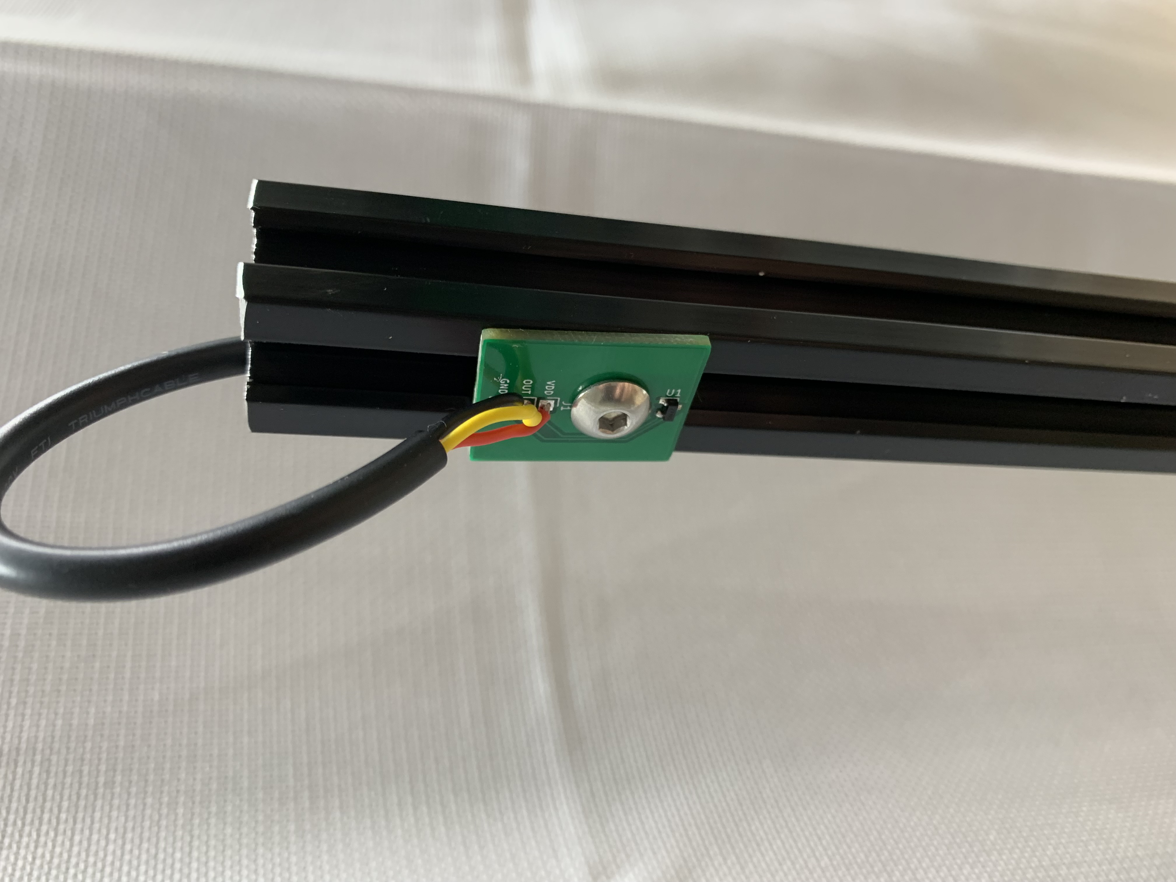
Mount the Up Sensor
Mount the up sensor using an M5x6 button head screw >20mm from the top of bar B.
Place the Carriage on Bar B
Push the carriage onto bar B. Make sure the up sensor cable goes under the back wheel. Loosen the M5x50 screw of the back V-wheel. Tighten the adjustment screws until the wheel pushes into the V slot. Re-tighten the M5x50 screw.
Add Cable Holders
Mount two cable holders with M5x8 screws to hold the up sensor cable in place.
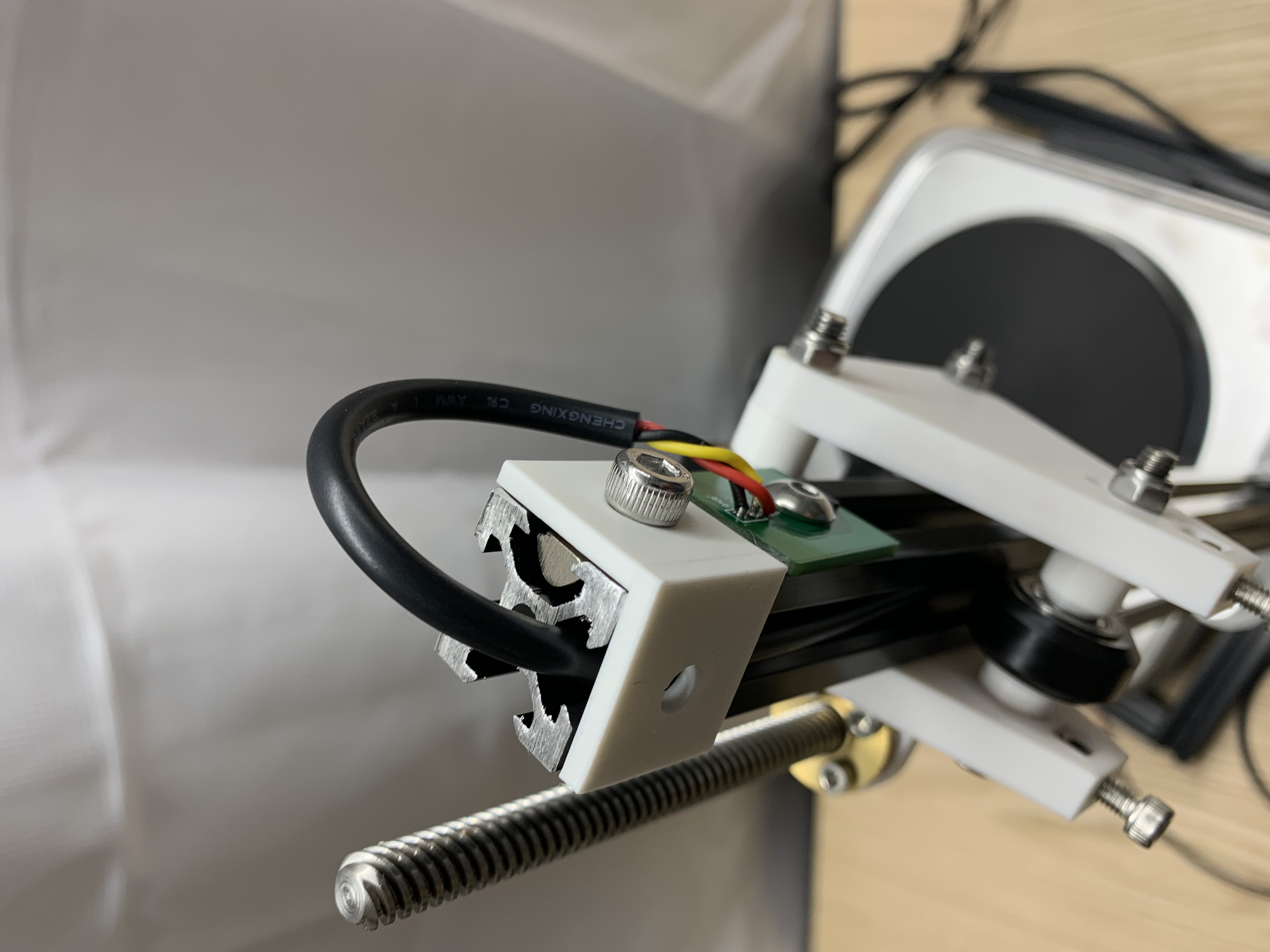
Install the Lead Screw
Screw the lead screw through the lead screw nut and then secure the set screws on the 8mm side of the coupler.
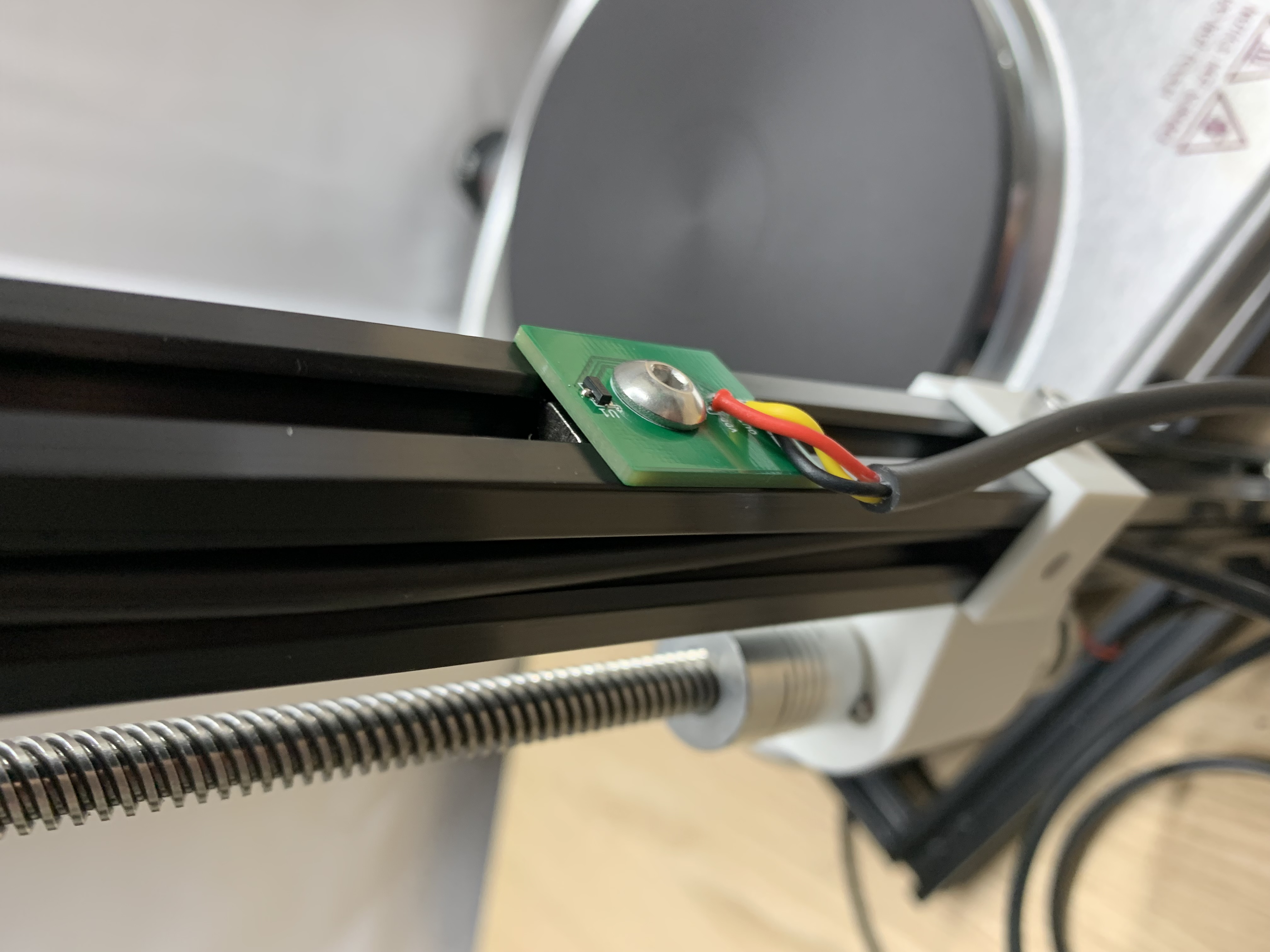
Mount the Down Sensor
Use an M5x6 button head screw to mount the down sensor.
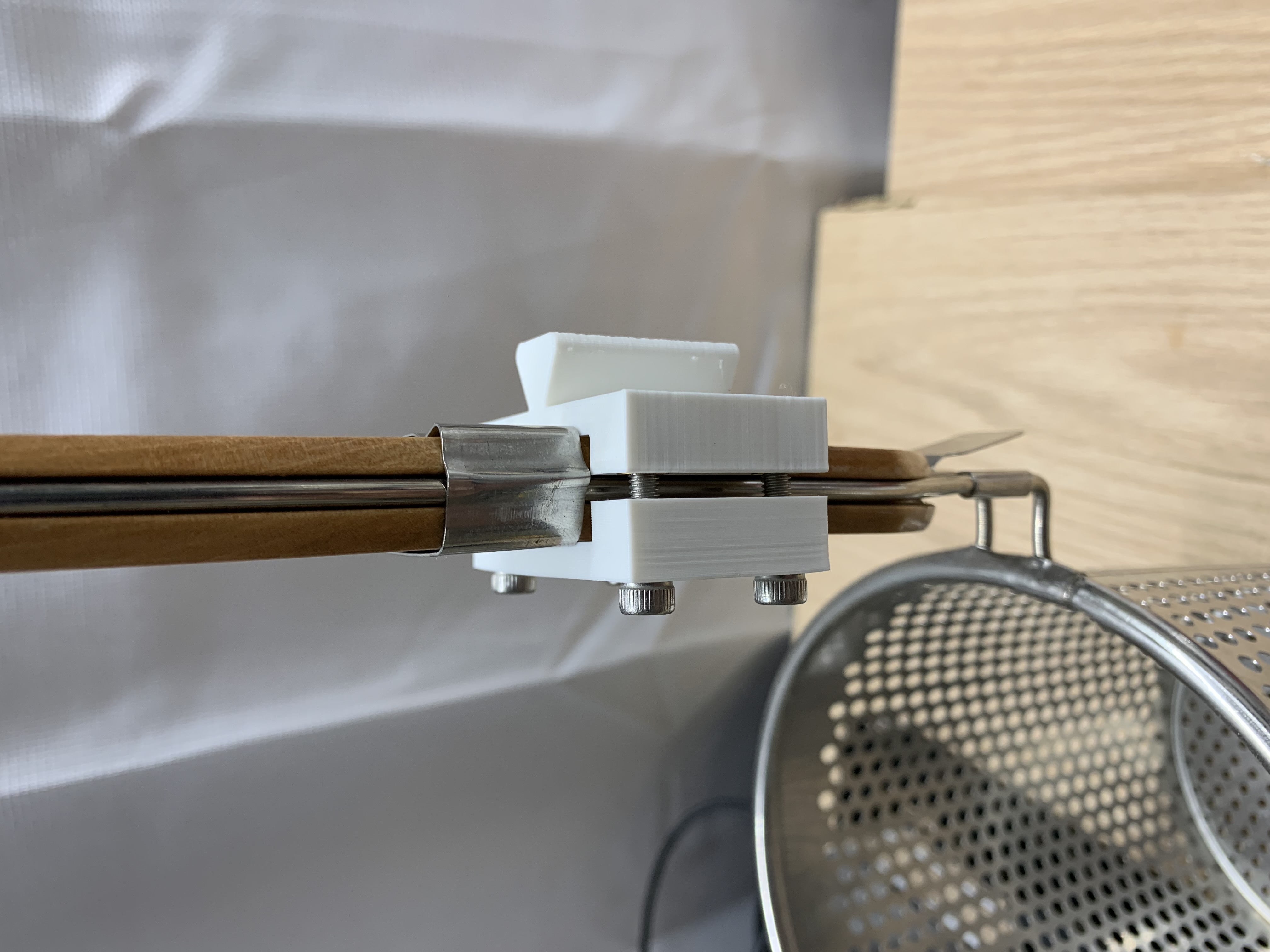
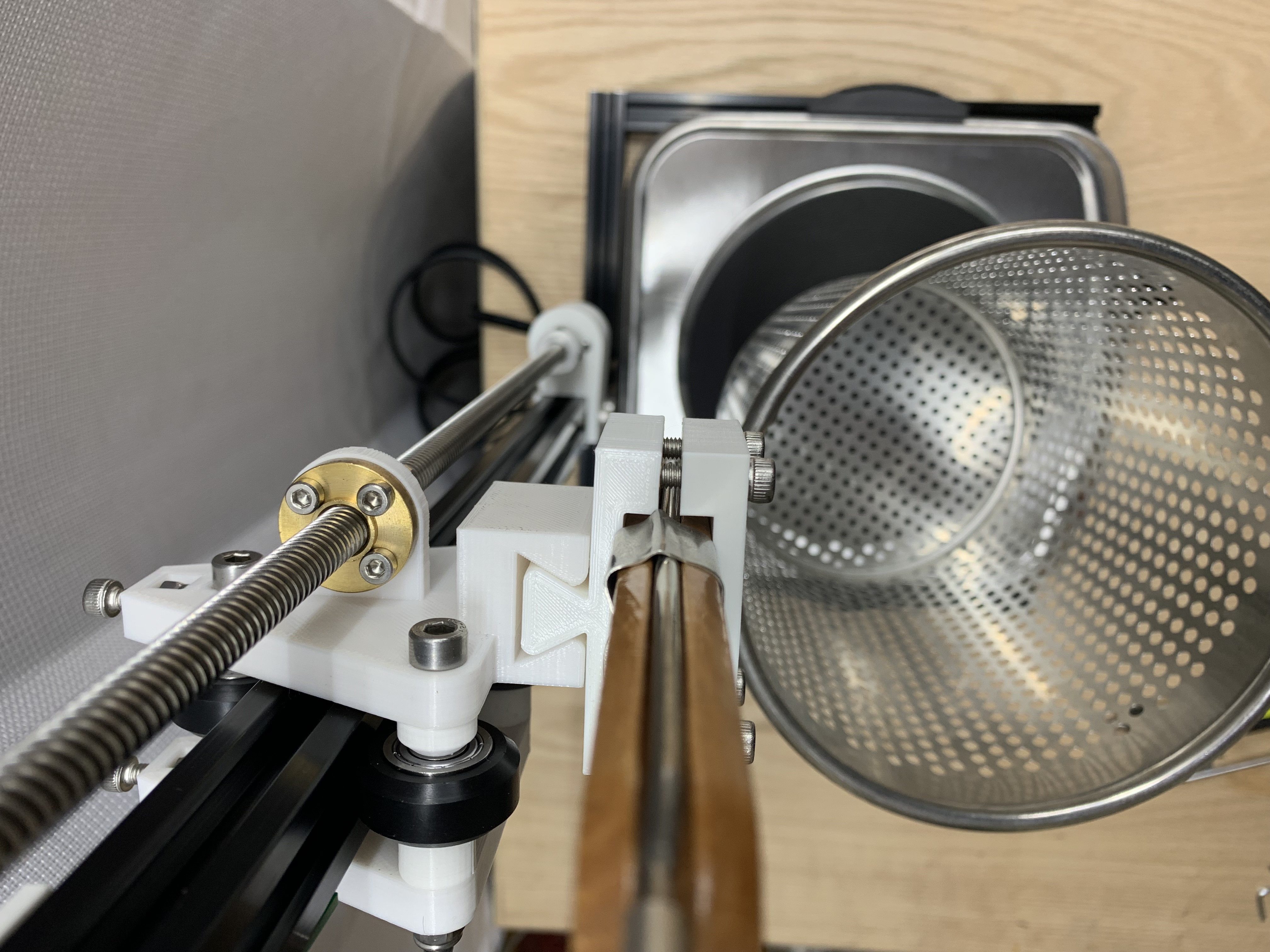
Clamp the Strainer
Push 4 M4 heat-set inserts into the clamp back. Use 4 M4x20 screws to clamp the strainer handle between the clamp front and clamp back. Slide the assembly into the carriage.