Electrical Assembly
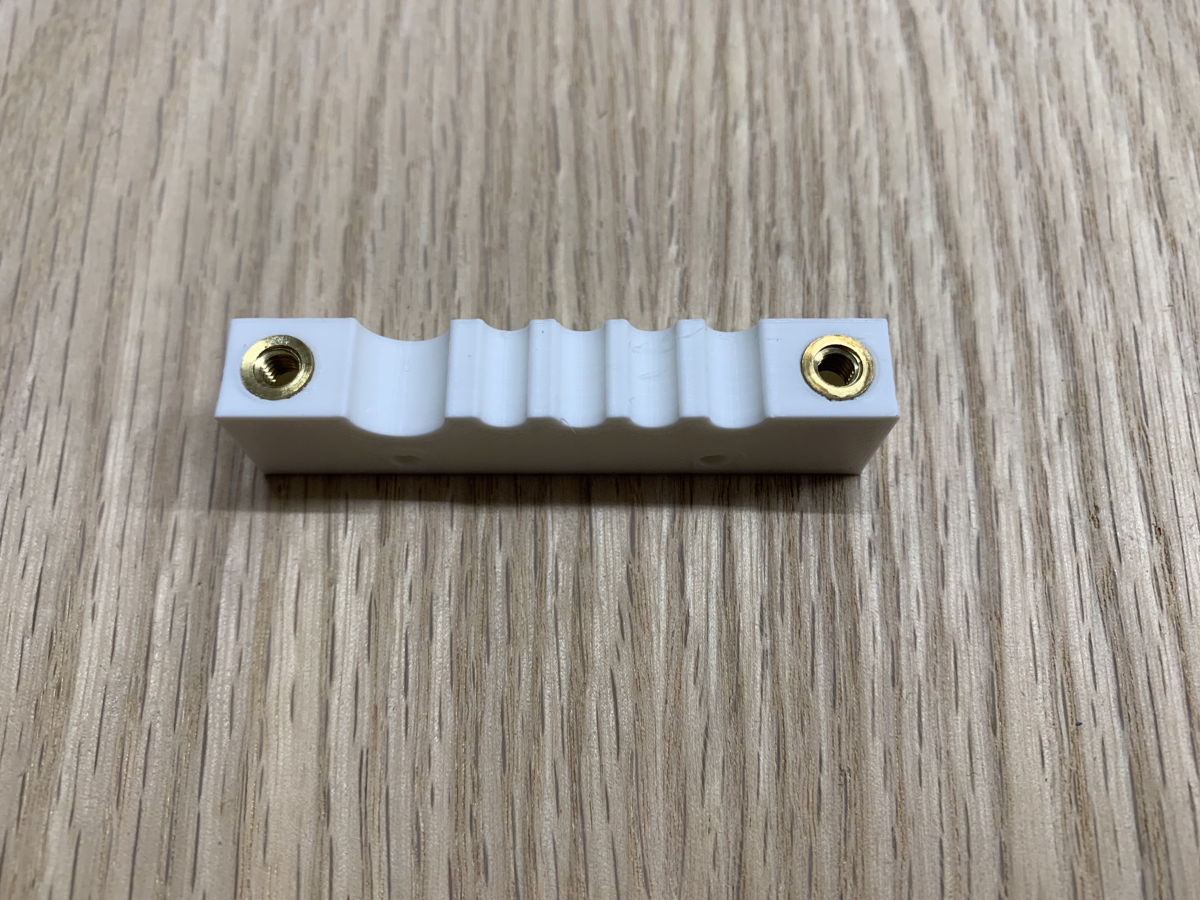
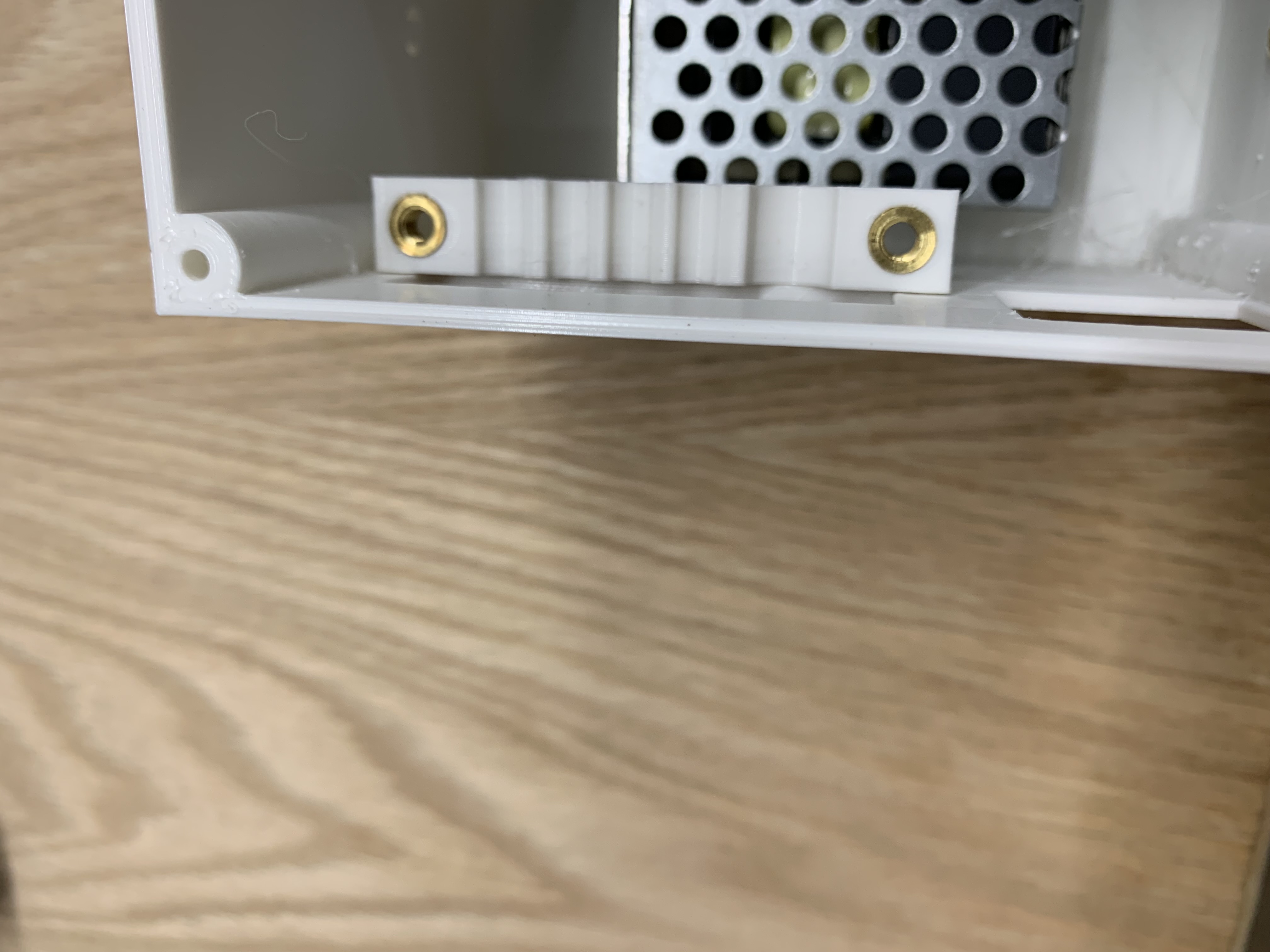
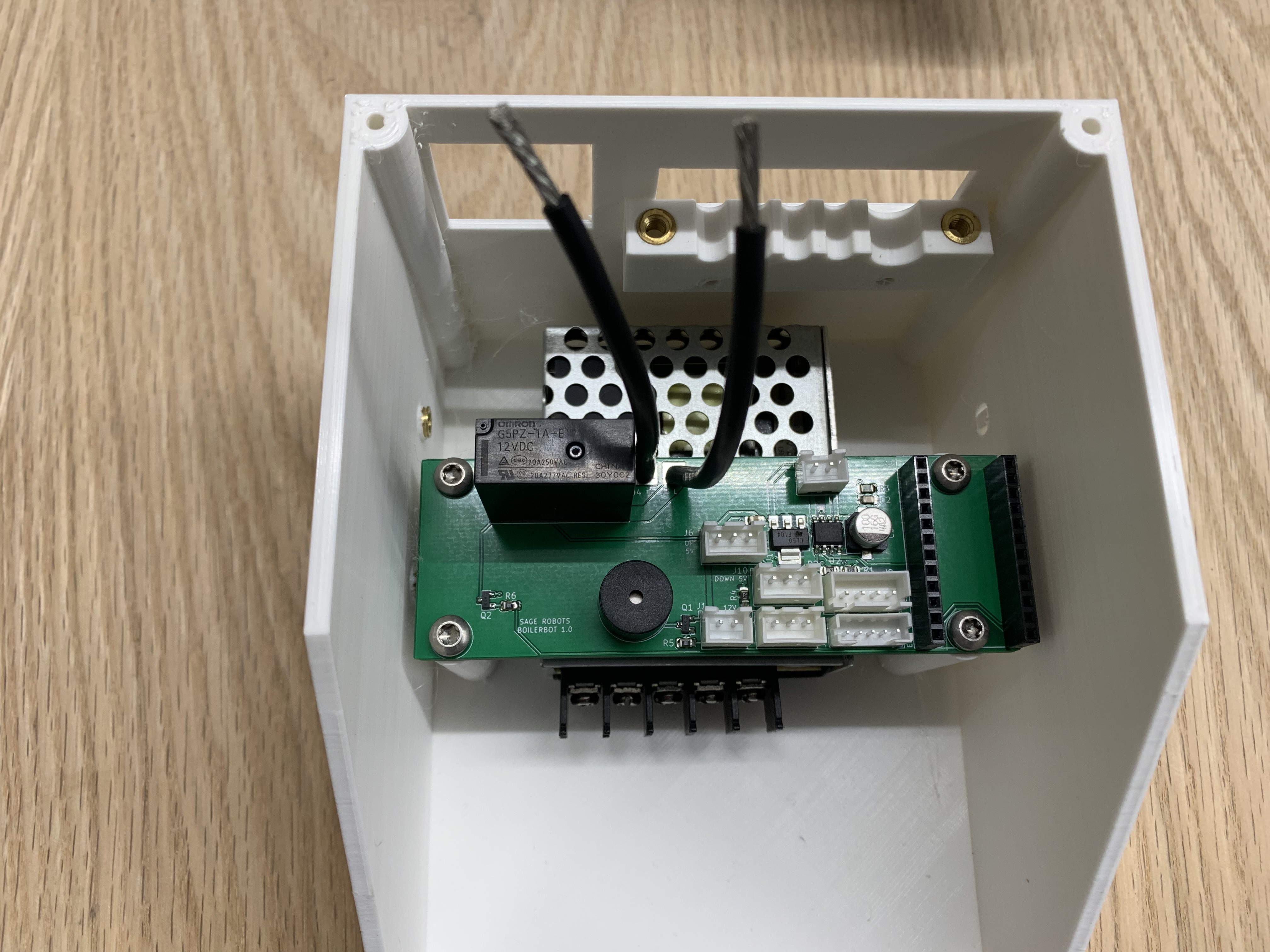
Attach Lower Cable Entry
Push 2 M4 heat-set inserts into the lower cable entry. Use 2 #6 plastic screws to mount it on the inside of the lower enclosure.
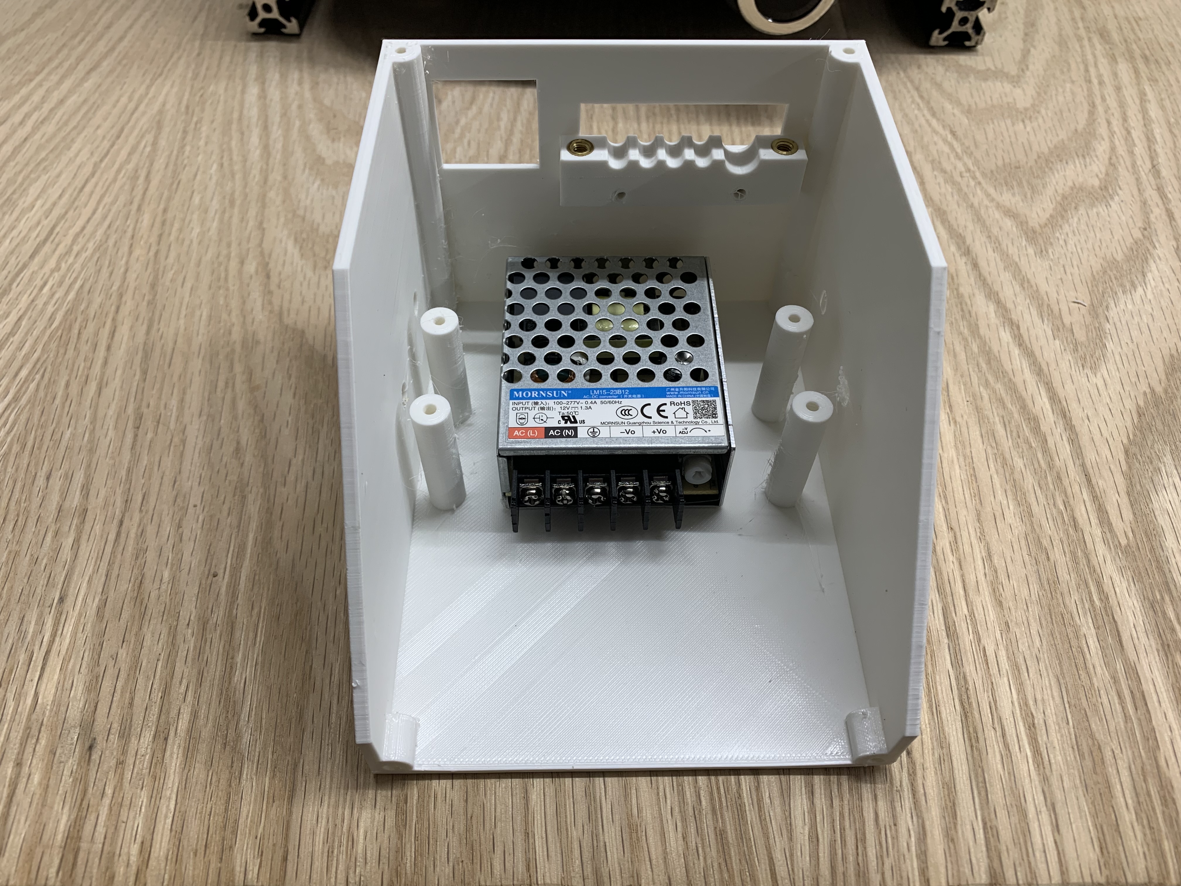
Mount Power Supply
Mount the power supply to the lower enclosure using M3x6 flathead screws.
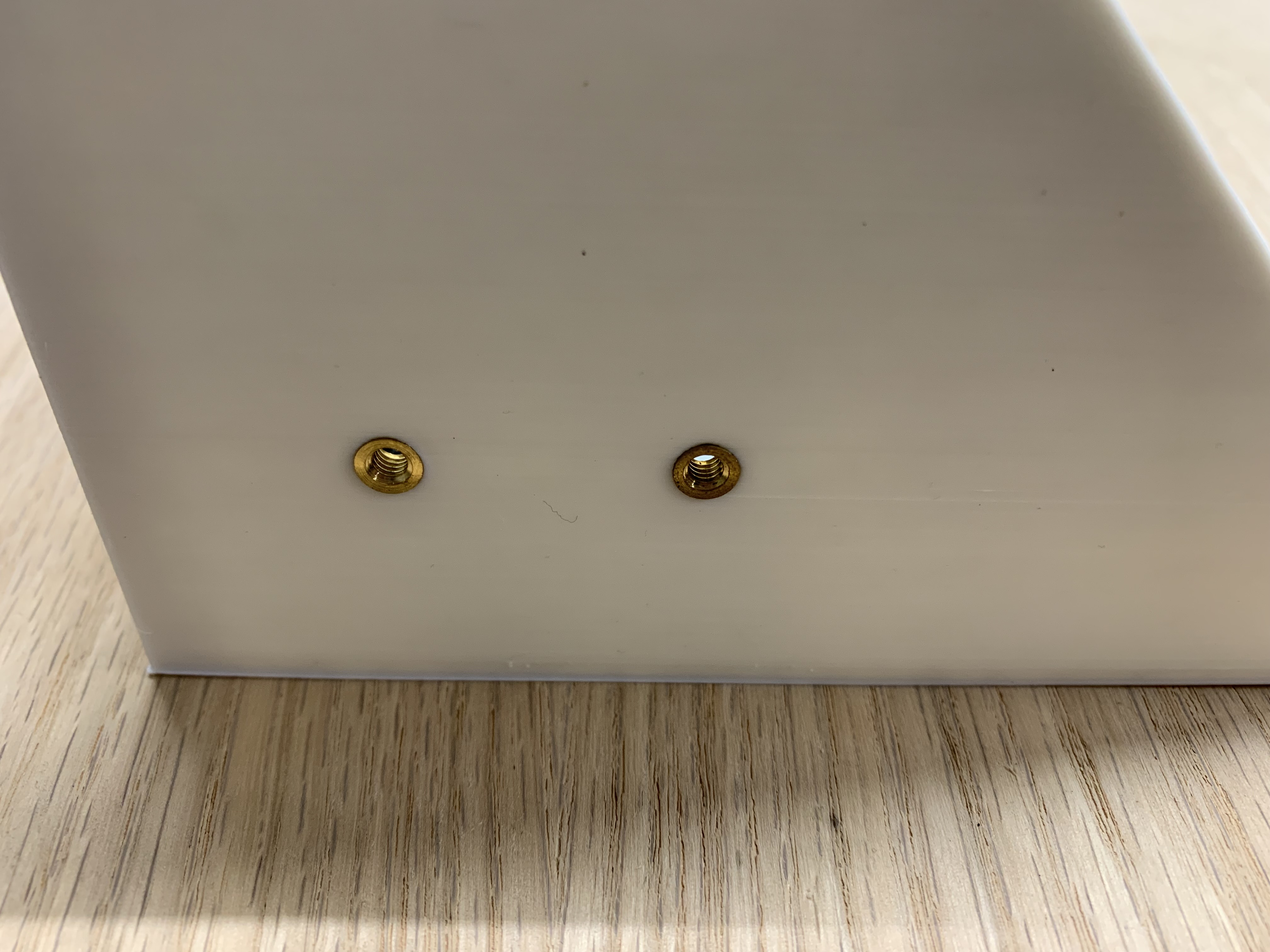
Add Mounting Inserts
Push 2 M4 heat-set inserts into the lower enclosure. These will be used to mount the enclosure to the frame.
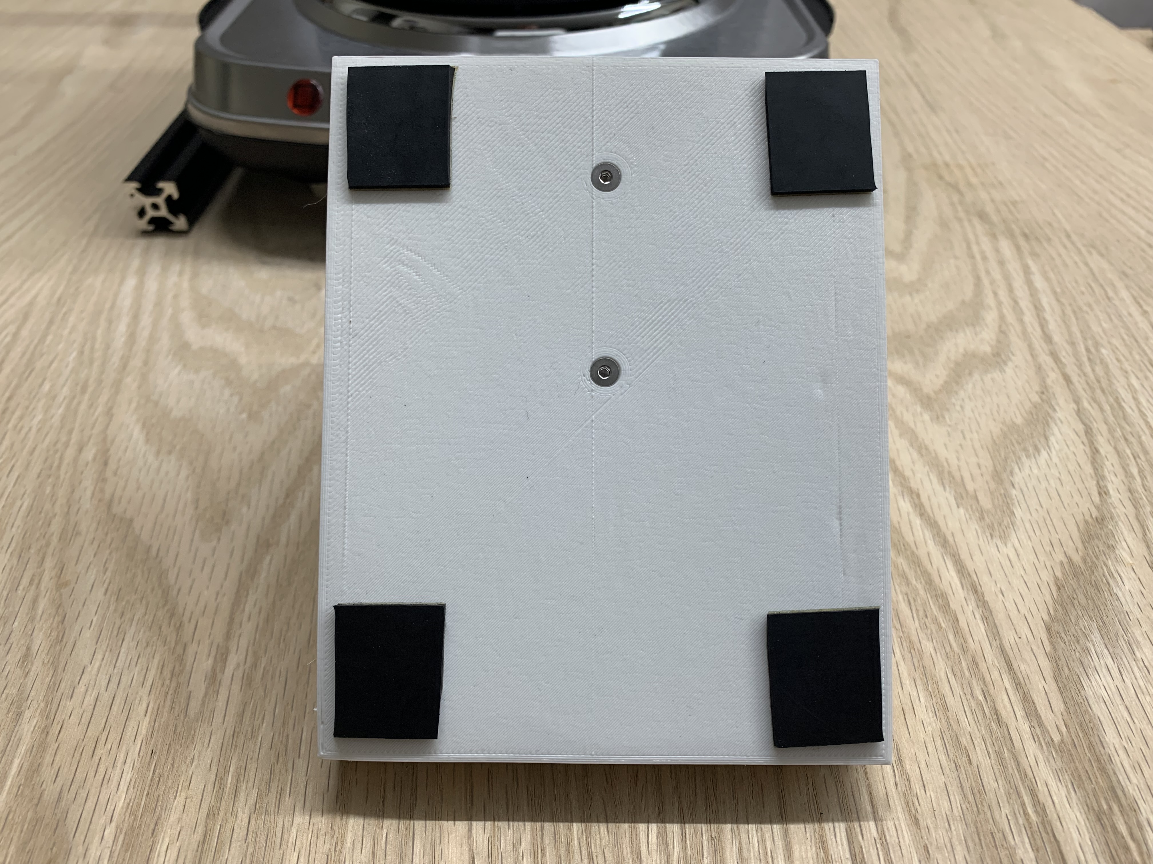
Add Rubber Pads
Cut 4 pieces of adhesive-backed rubber and stick them to the corners of the enclosure.
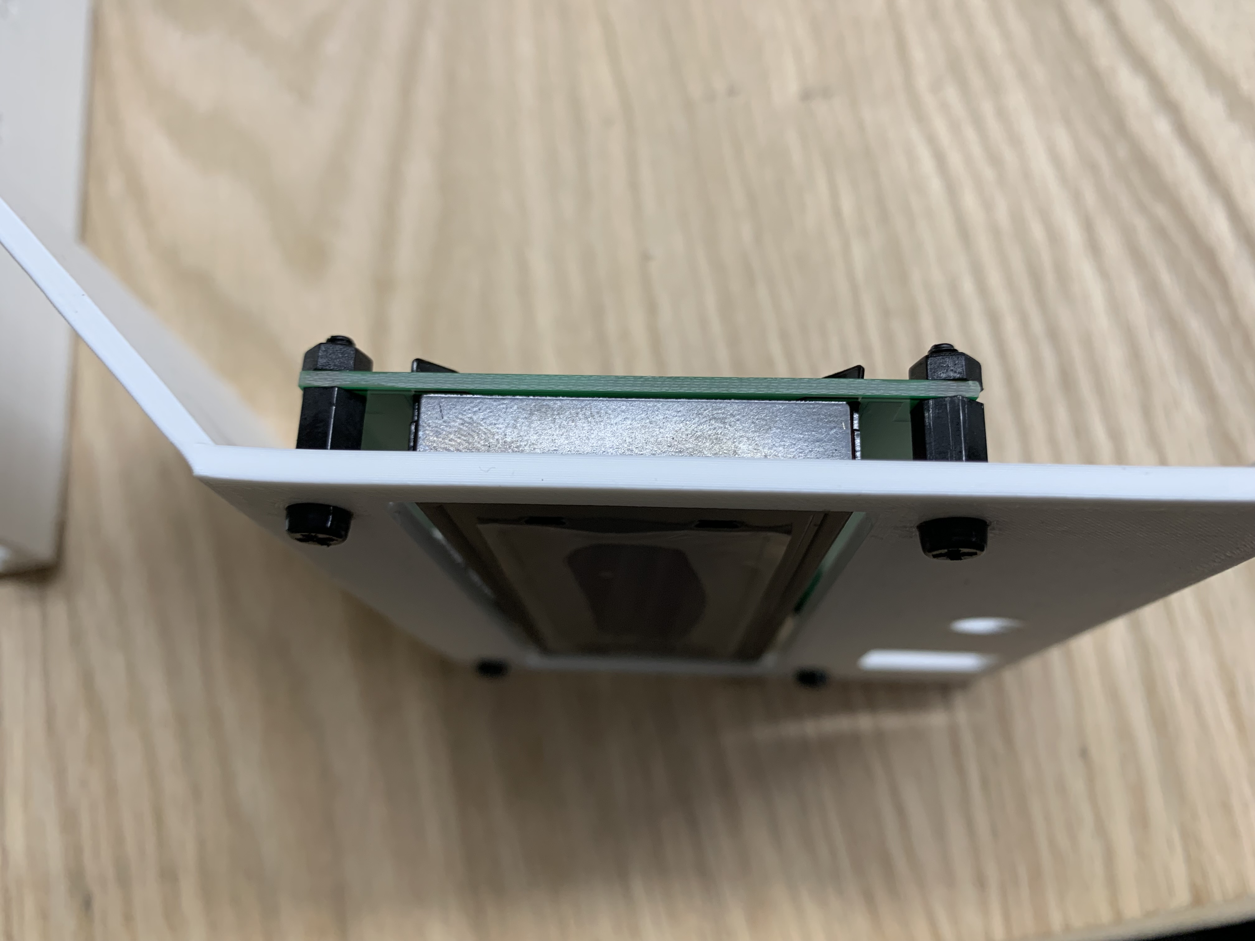
Mount PCBA
Mount the PCBA in the enclosure.
Mount Components on Upper Enclosure
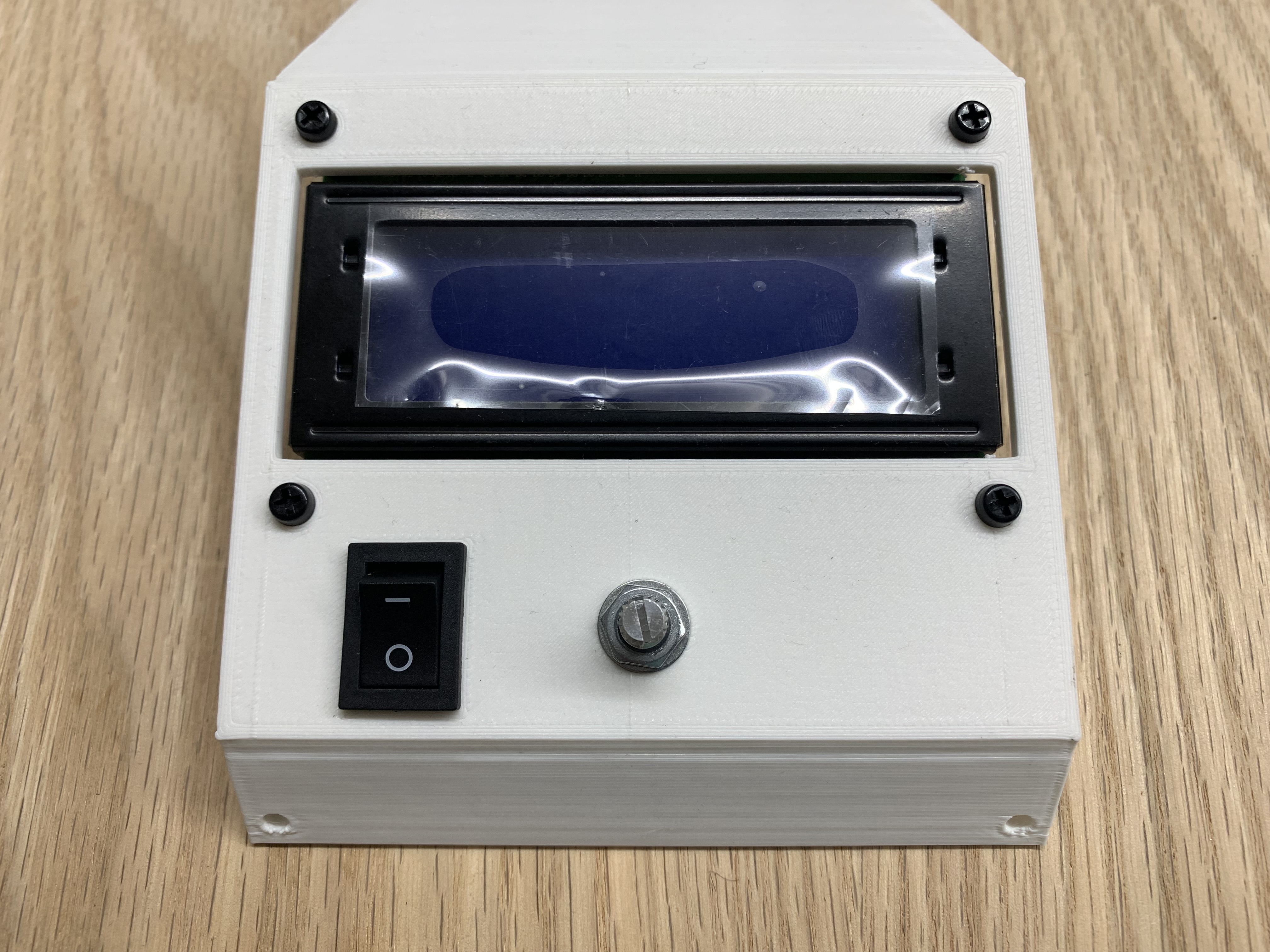
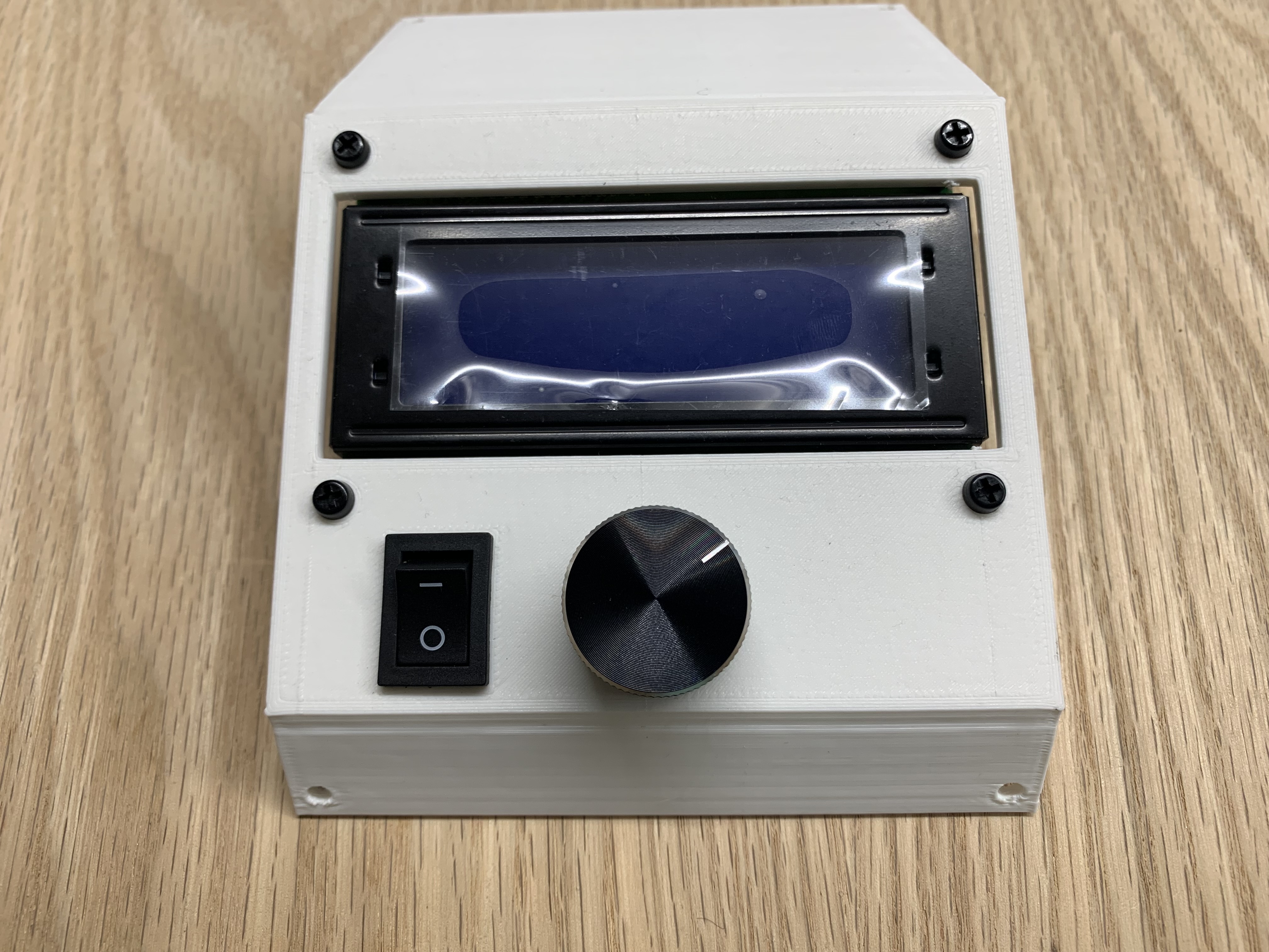
Use 4 M3x8 standoffs to mount the LCD to the upper enclosure. Also mount the encoder and power switch.
Push Knob onto Encoder
Push the knob onto the encoder shaft firmly. Support the back of the encoder to prevent the upper enclosure from cracking.
Wire the LCD, Encoder, and Power Switch
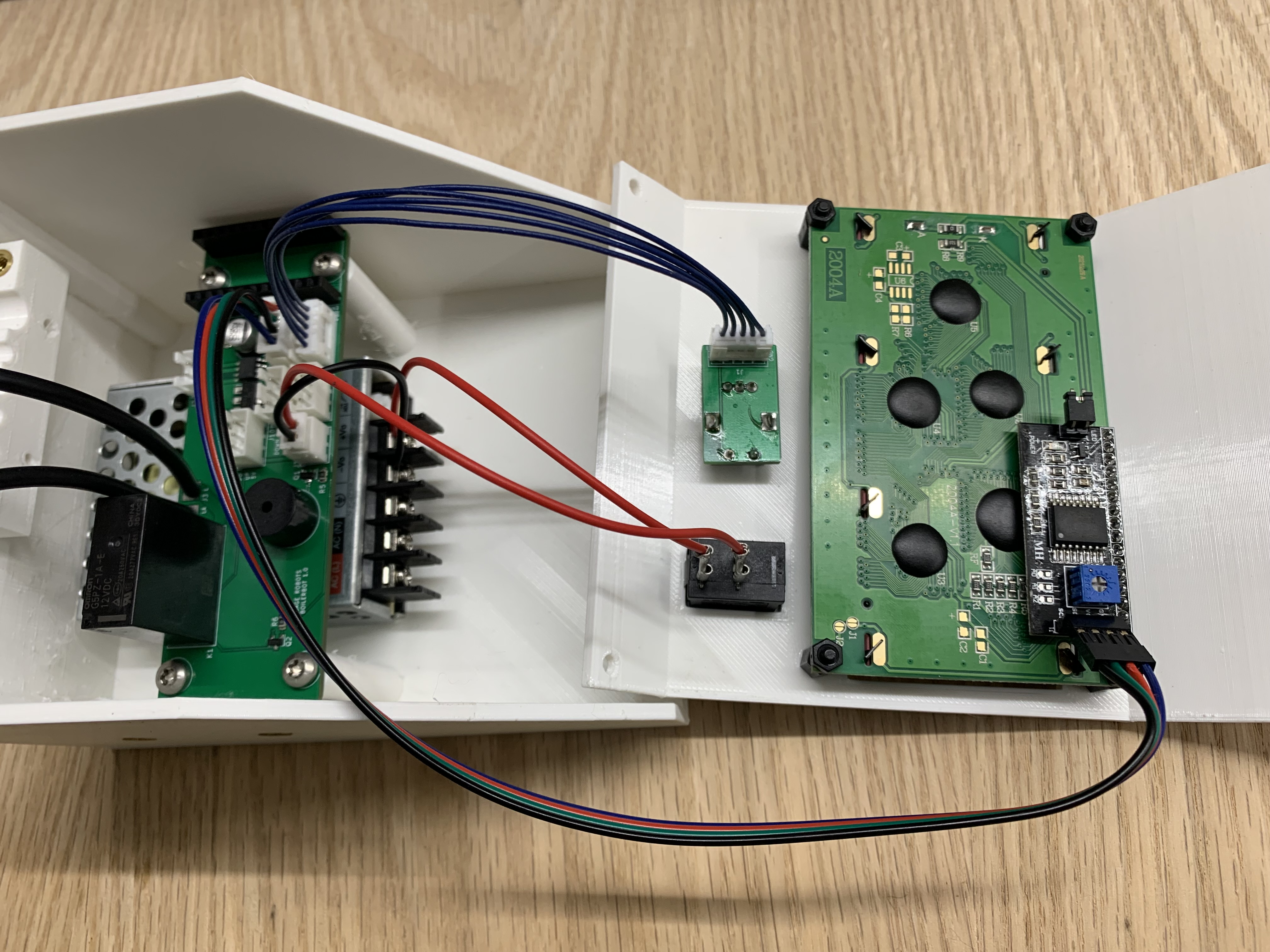
Wire the LCD with the LCD cable, the encoder with the encoder cable, and the power switch with quick disconnects as shown.
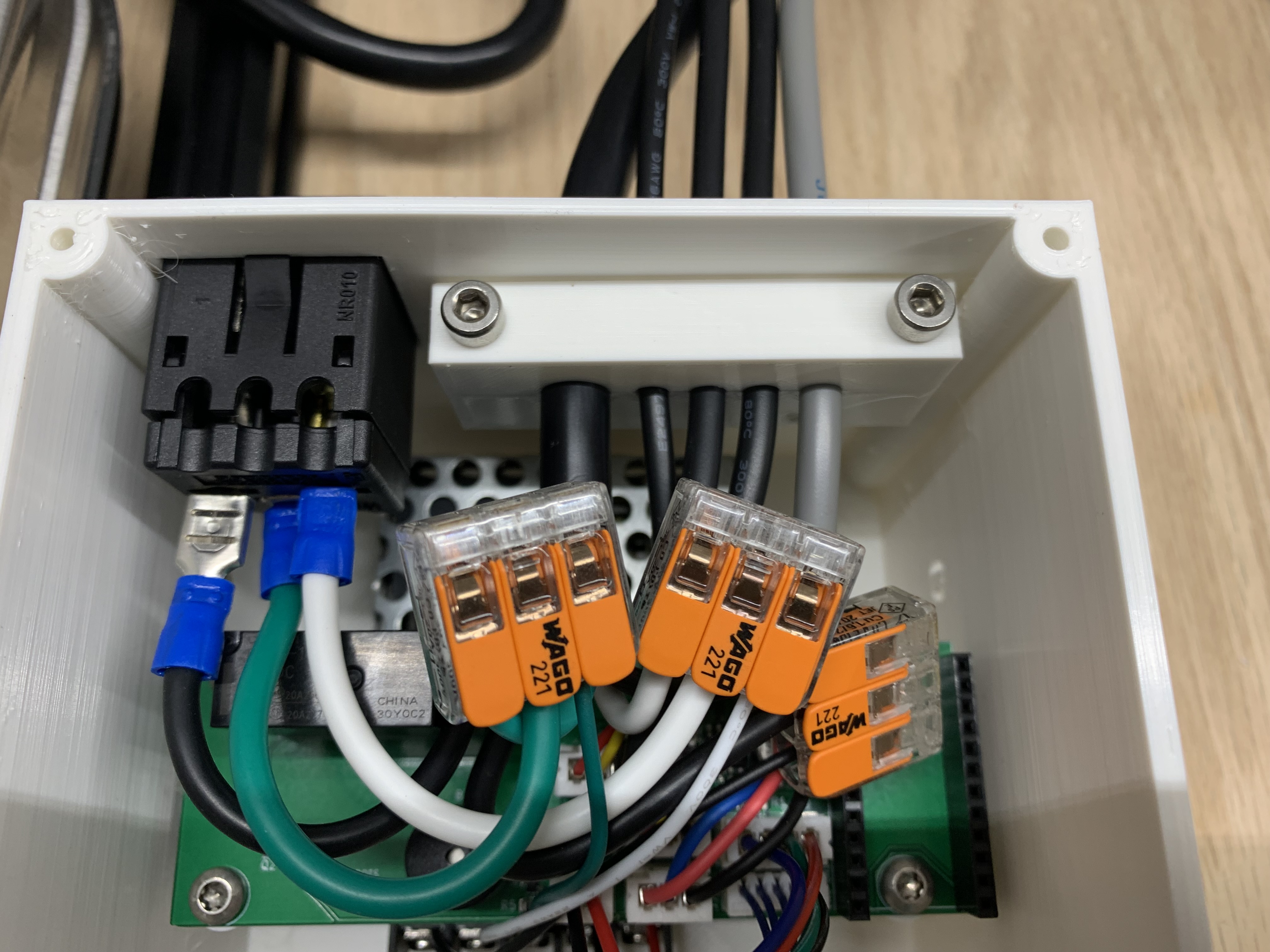
Wire the Power Cable
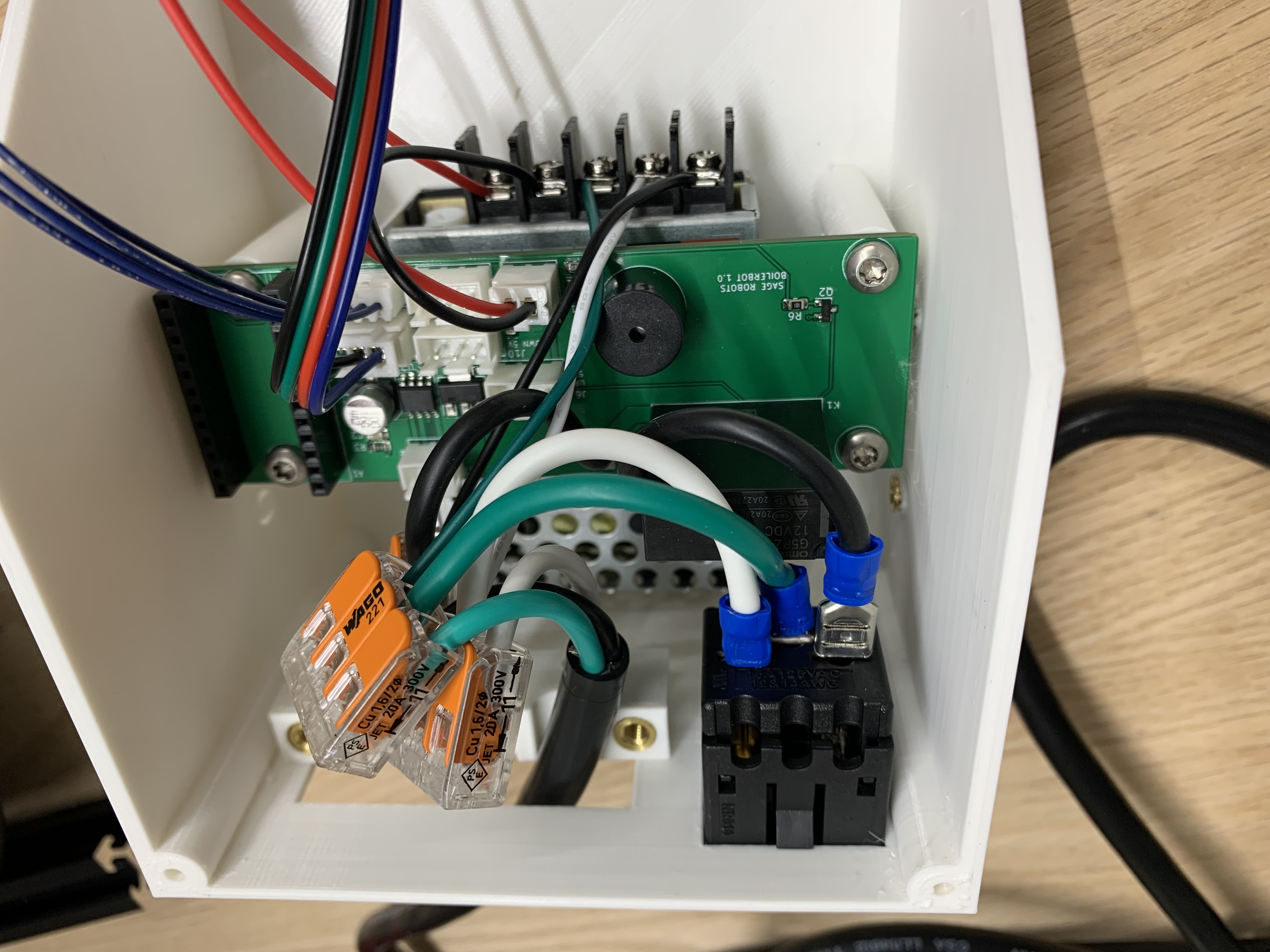
Use lever nuts to connect the power cable to the PCBA, power supply, and receptacle. Push the receptacle into place after it is wired.
Mount the Enclosure
Mount the lower enclosure to the frame using the enclosure brackets, 2 M5 t-nuts, 2 M5x8 button head screws, and 2 M4x8 button head screws.
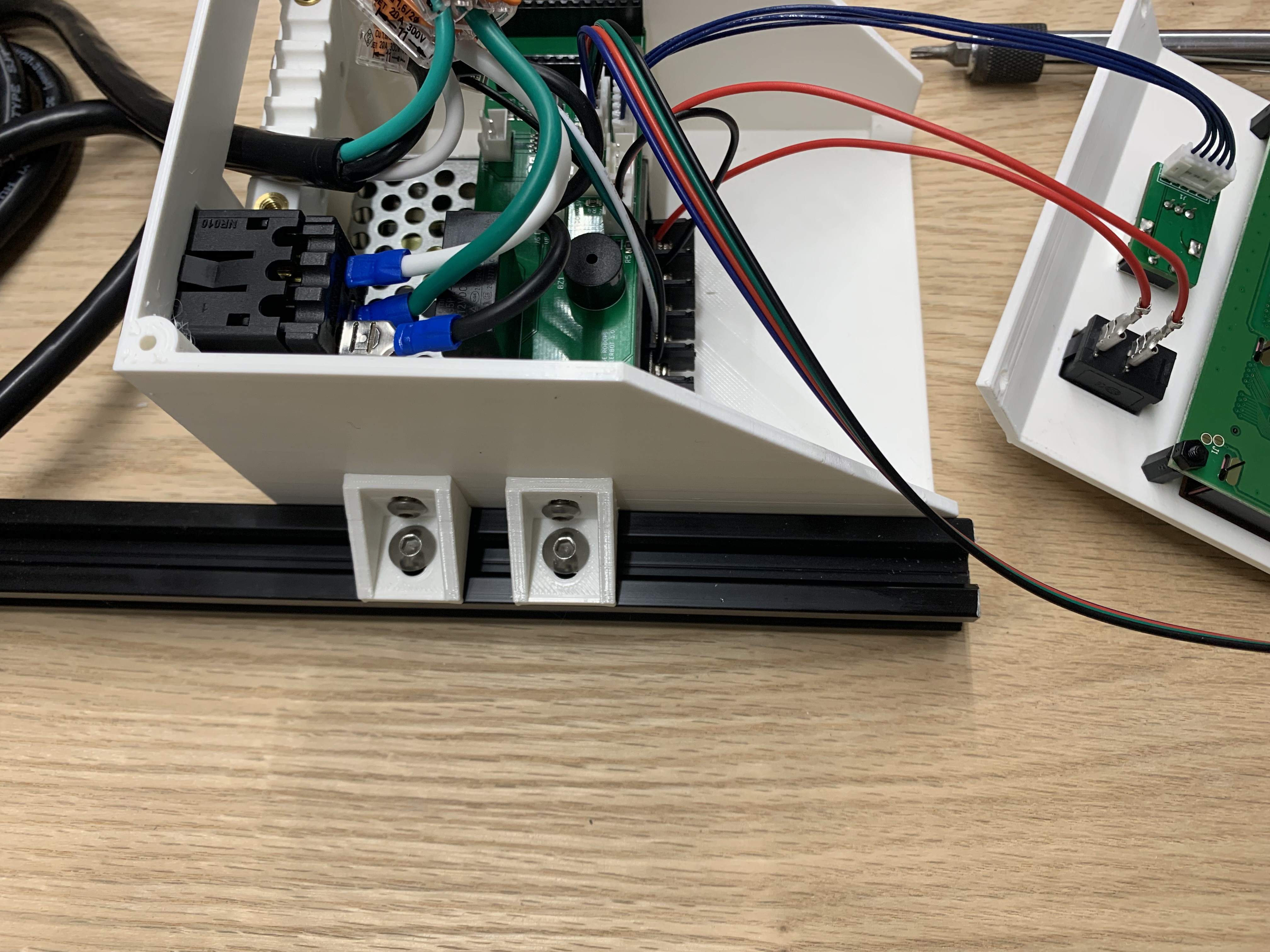
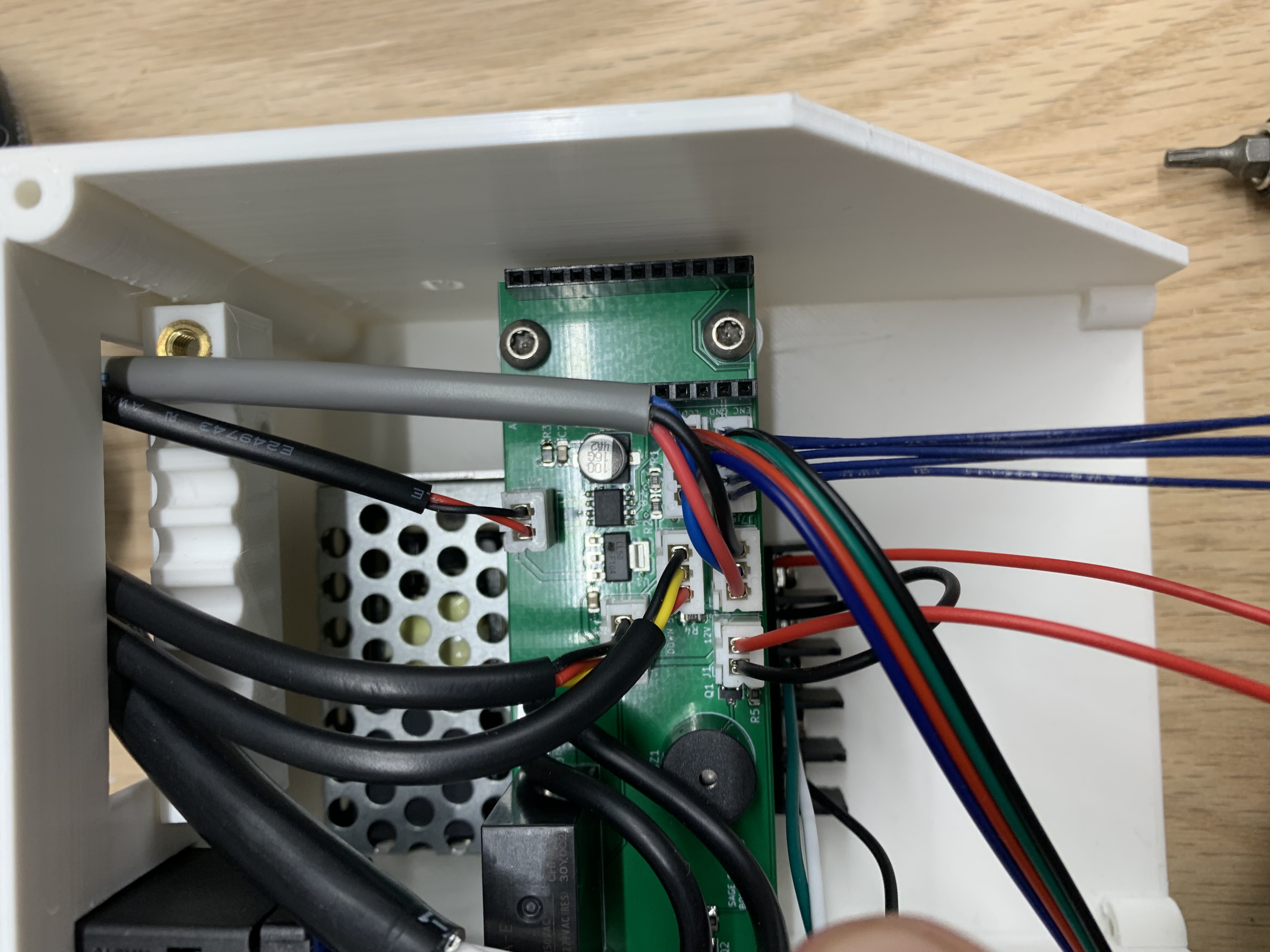
Connect the Motor and Sensor Cables
Connect the motor, up sensor, down sensor, and temperature sensor as shown.
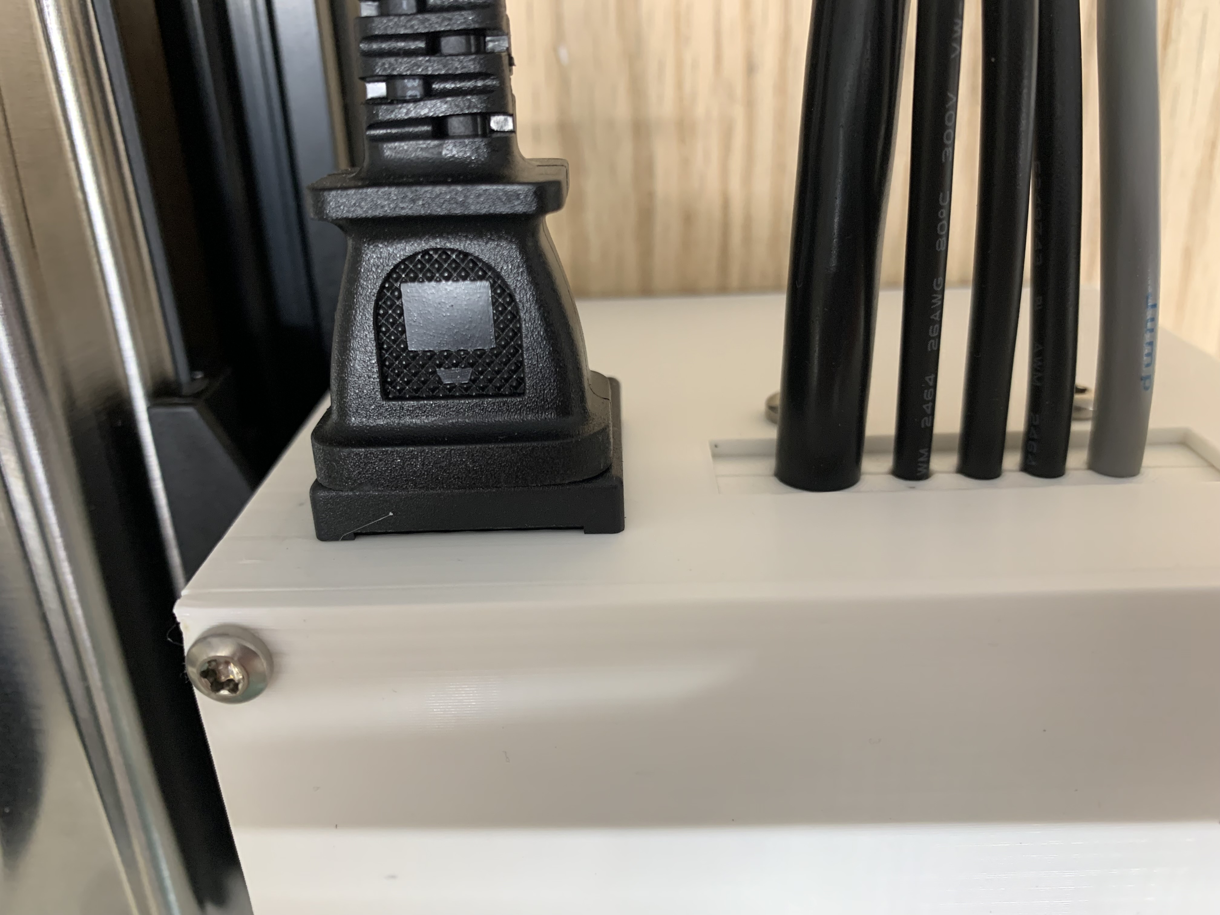
Tighten the Upper Cable Entry
Clamp all the cables with the upper cable entry using 2 M4x16 screws.
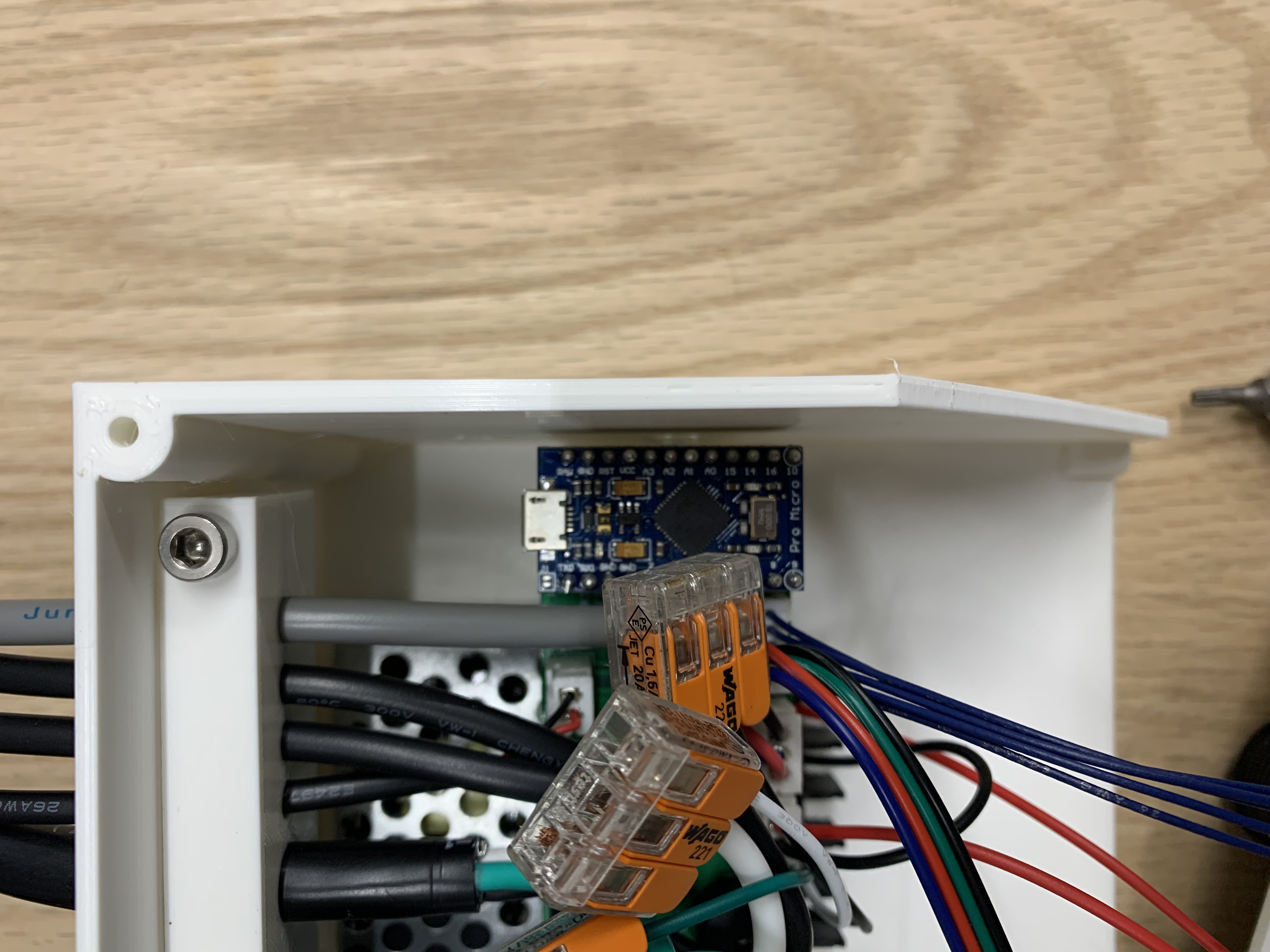
Upload the Arduino Code
Upload the code to the Pro Micro and push the microcontroller into the PCBA.
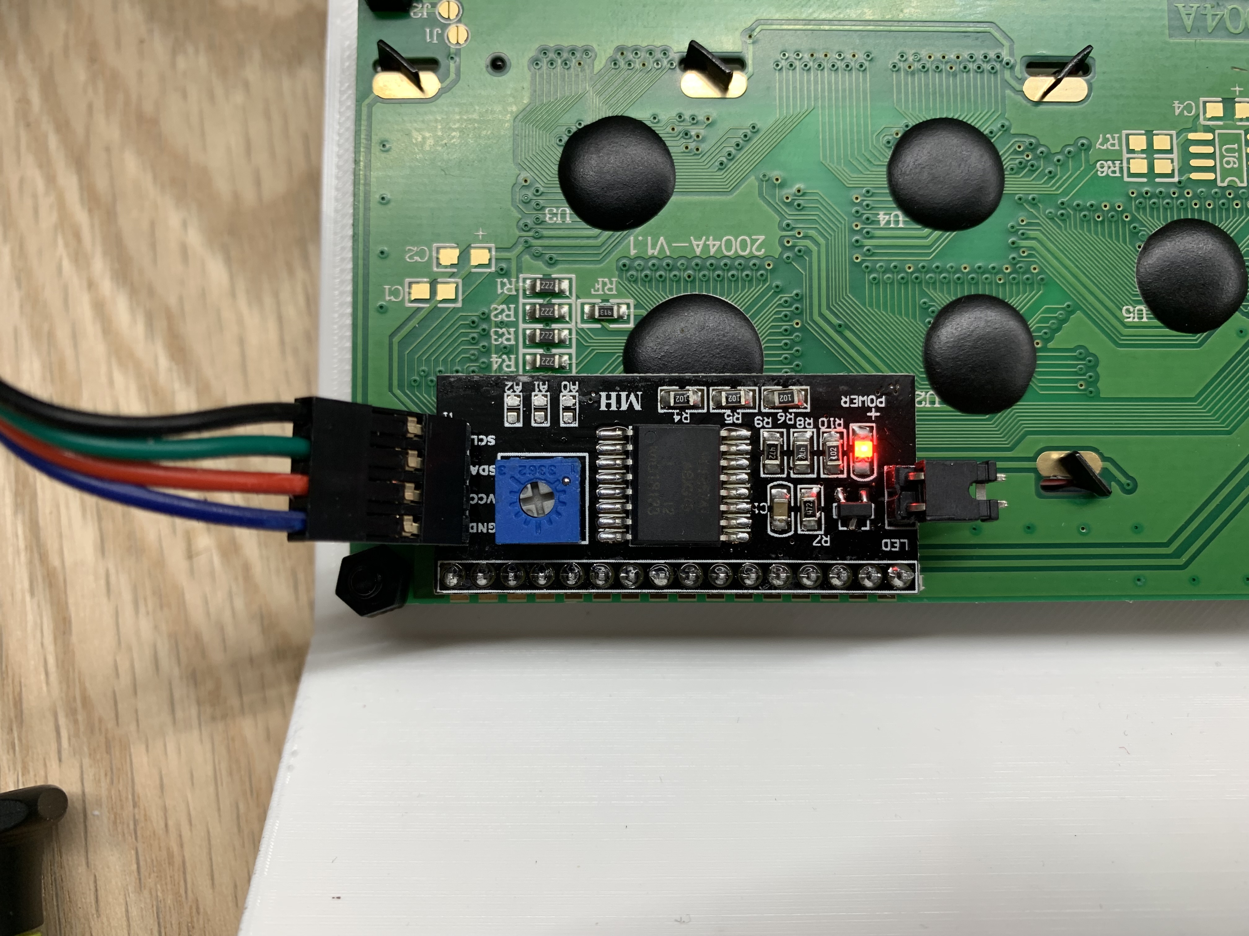
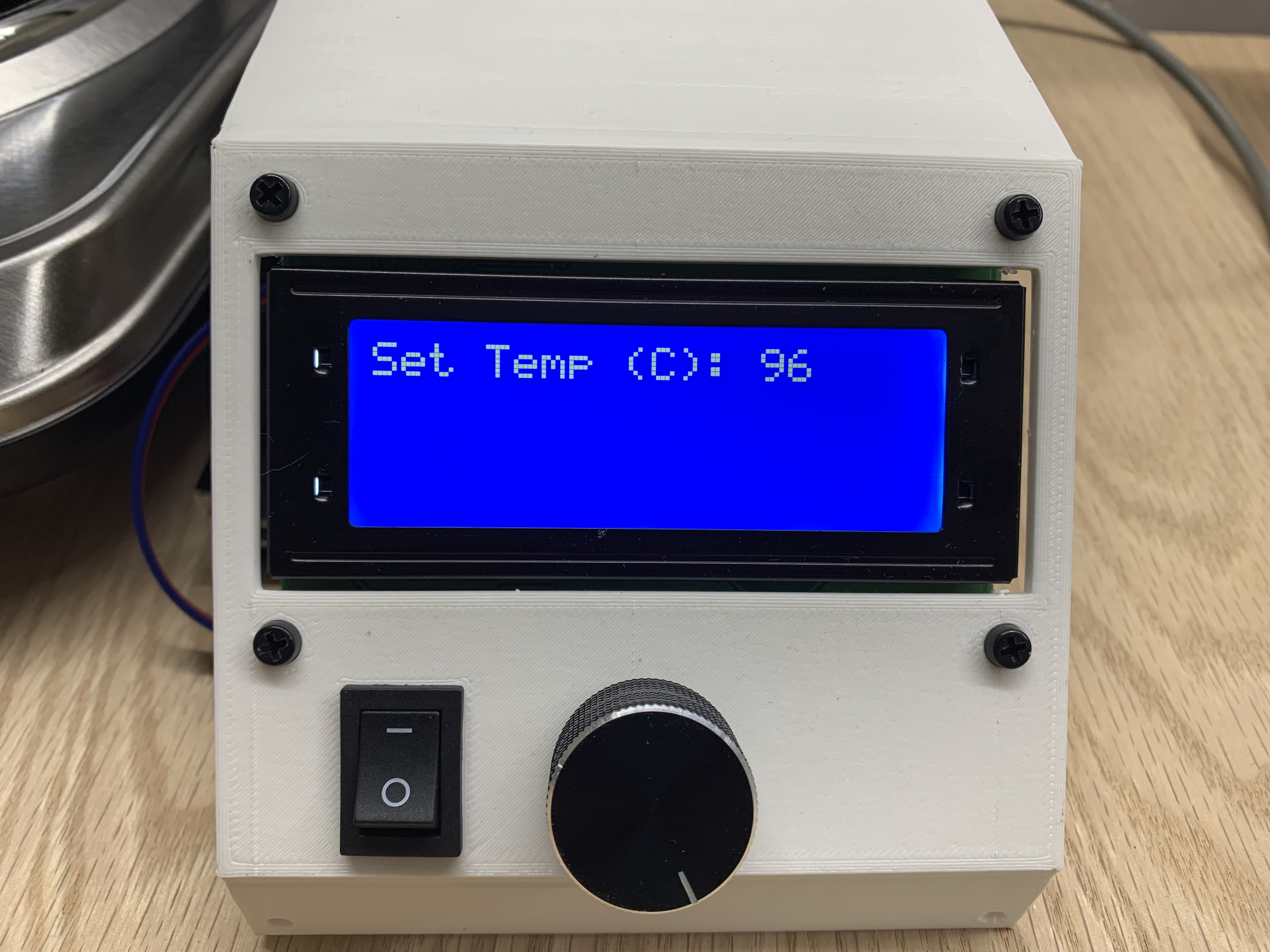
Adjust the LCD Contrast
Plug in the main power and flip the 12V switch on. Be very careful not to touch any exposed 120V contacts. Twist the potentiometer on the LCD board until the text on the screen is legible. Then unplug the power cord.
Close the Enclosure
Use 4 plastic screws to secure the upper enclosure to the lower enclosure. Also plug in the hot plate.
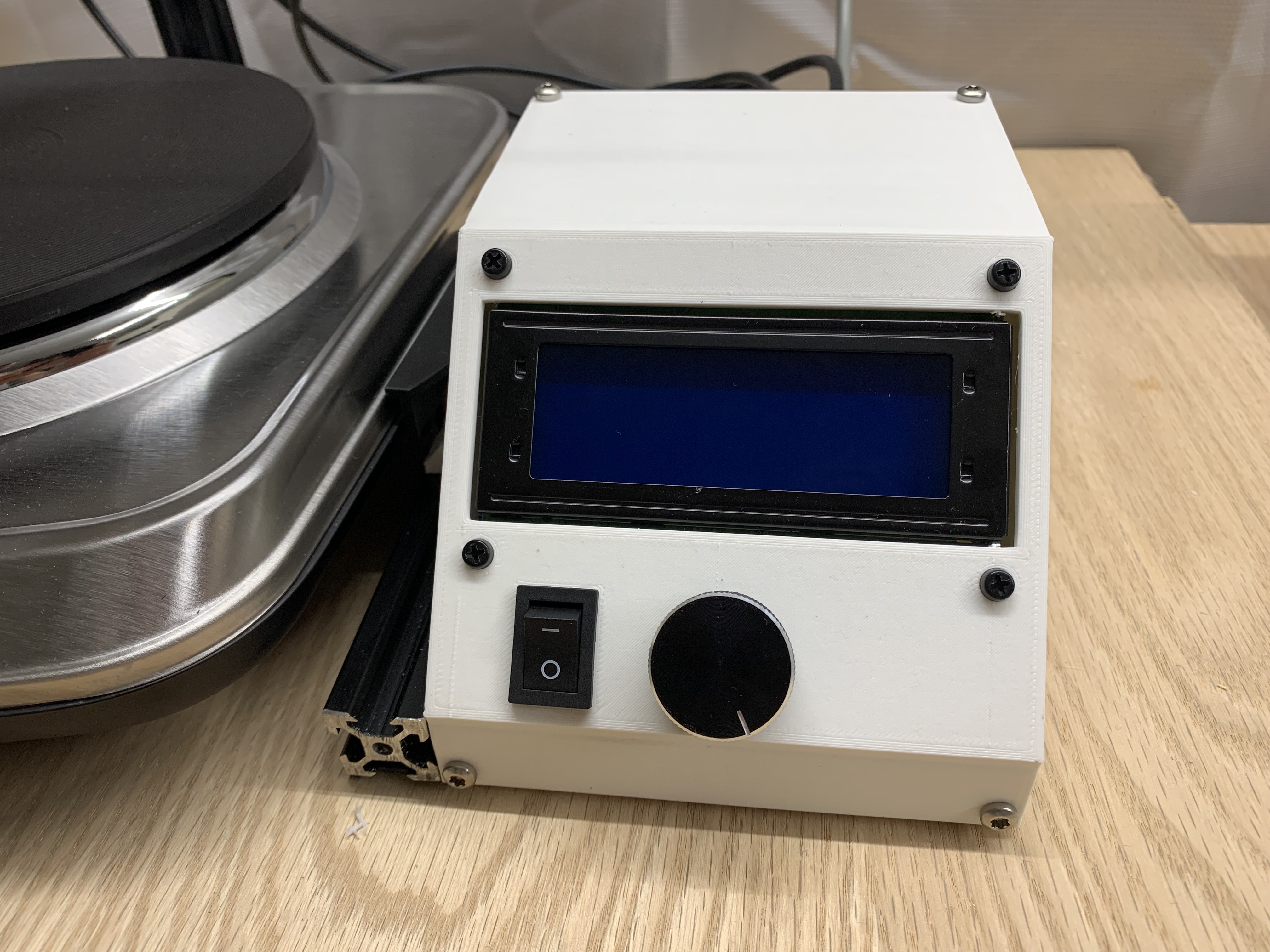
Test BoilerBot
The assembly is now complete. You can run at 20C for 10 seconds to test the motion. It will not need to heat because this is room temperature. The down sensor should be adjusted so the strainer does not get pushed out of its holder.